Elecraft KIO2 User Manual
Page 6
6
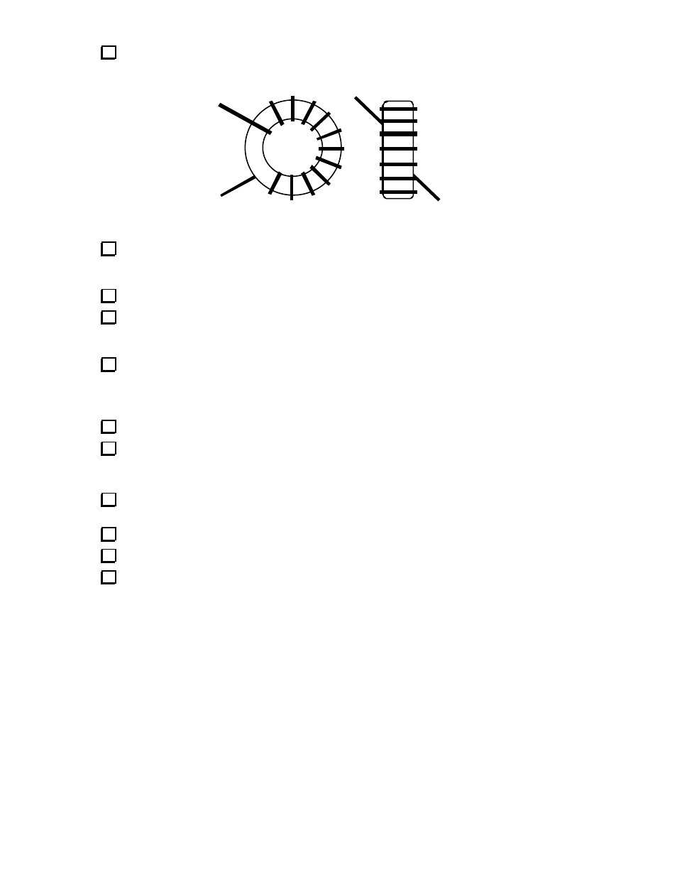
Wind 12 turns of #26 red enamel wire (7", 18 cm) on the FT23-43 toroid core (L5) as shown in Figure
3. Avoid scraping the wire against the core as you wind. The turns should occupy 80-90% of the core.
Figure 3
Trim the leads of L5 to about 1/2" long. Remove all of the enamel coating to within about 1/16"-1/8"
of the core, using a soldering iron to heat-strip the thermaleze wire. (An alternative is to use sandpaper.)
Tin the leads, and make sure they appear clean and shiny.
Install and solder the toroid vertically as indicated by L5's component outline.
On the top side of the board, to the left of C7, you'll find a small arrow. This arrow identifies a pad for
use in grounding the case of J1 (the DB9 connector). Insert a discarded component lead into this hole from
the top side of the board, then solder it at this pad.
Fold the free end of this ground lead over the top of the DB9 connector case, keeping it well away
from J1's pins. Solder the ground lead to the DB9 case. Trim excess lead length on both sides of the board.
AUX2 PC Board Assembly
Locate the smaller PC board, labeled "AUX2" on the bottom side.
On the top side of the board, install the following components:
__ C1 (0.1 µF, "104")
__ C2 (.01 µF, "103")
__ L1 (15 µH, BRN-GRN-BLK).
On the bottom side, install J1, a 10 pin female connector. Make sure J1 is flush with the board, then
solder one pin only on the top side.
If J1 is not flush with the board, re-heat the soldered pin while pushing down on the connector.
Solder the remaining pins of J1.
On the top side, install P1 (10-pin male connector). Make sure it is flush with the board, then solder.