Green wire aux2 pcb to kat2 to kio2 – Elecraft KIO2 User Manual
Page 16
16
KIO2 Installation
Figure 9 (previous page) shows where the KIO2 board will be installed in the K2's top cover. The KIO2's
female D connector will be mounted in the hole labeled "AUX I/O" on the rear panel. The ATU's control
cable will plug into the AUX2 board (if applicable). There is no need to remove the battery or ATU.
Place the top cover upside down on a cloth or other soft surface to protect the finish.
Disconnect the KIO2/AUX2 assembly from the K2.
Position the KIO2 module as shown in Figure 9. The side of the board with the crystal (X1) should be
facing up; the side with the cable connections faces down. If you have the module placed correctly, the
female connector will be aligned with the trapezoid-shaped AUX I/O panel hole. Note: The module may be
a very tight fit if you have the battery installed.
Secure the KIO2 module using the hex male-female standoffs. Do not use washers of any kind, as
they will prevent the serial I/O cable from being fully inserted into the KIO2 connector. Tighten the
standoffs using pliers or a socket driver. Avoid over-tightening, which may strip the standoff threads.
If a battery (KBT2) is installed, route the 8-conductor cable around it as shown. If an ATU (KAT2) is
installed, position its RF cable as shown, and make sure this cable is not shorting to the KIO2 board.
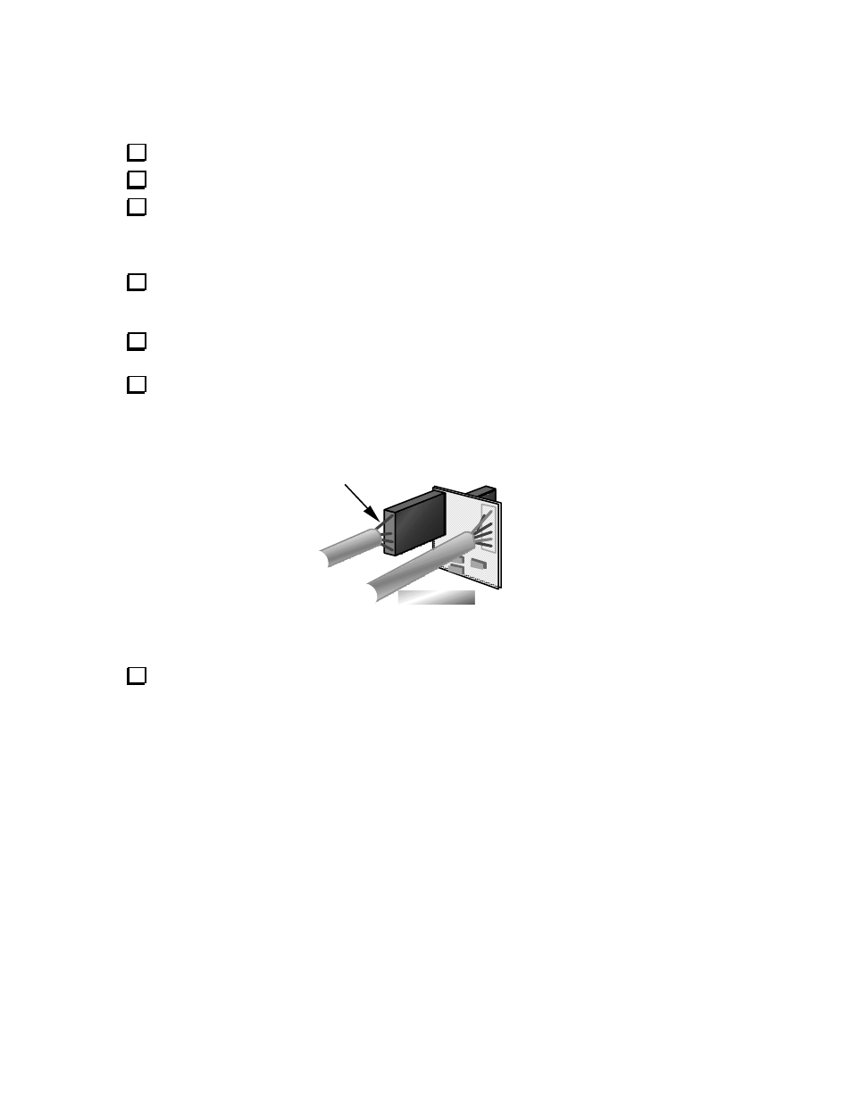
If you have the antenna tuner installed, plug its control cable into P1 on the AUX2 board as shown in
Figure 10. Orient the ATU connector as shown, with the green wire at the top. Make sure the antenna
tuner's connector is mated with all 10 pins of P1 on the AUX2 board.
GREEN WIRE
AUX2 PCB
TO KAT2
TO KIO2
Figure 10
Use the provided cable ties to keep all option cables in place. If any of the cables lay across the
RF board once the top cover is re-installed, they could cause spurious signals in the receiver. The best
location for the cable ties depends on which options you have installed. If you have a battery installed,
make sure that the KIO2 cable runs along the side of the battery, just above the 2-D fastener (Figure 9).
You can bundle the KIO2 cable along with the red wires running to the battery on/off switch.