Elecraft KSB2 User Manual
Page 8
8
i
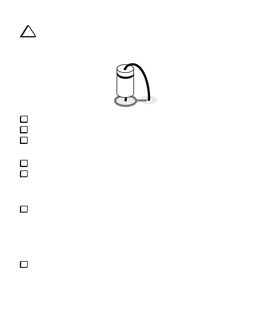
All diodes will be installed vertically as shown below. The anode lead will be inserted into the pad
enclosed by a circle. The cathode lead (banded end) must be folded down and inserted into the adjacent
pad, which is connected to the first pad by a white line. When installing diodes, check the Parts Placement
Drawing as needed to make sure that you're inserting the leads into the correct pads.
Install D3 and D4 (1N4148), both of which are near U5.
Install D5 (1N4148), on the left side of the board near C34.
Install D1 (1N4007), which is located near the middle of the board. As indicated by the short white
line, the cathode lead (banded end) goes into the pad to the left of the D1 label. (There are two other pads
nearby D1, so be careful to use the correct one.) Push the diode down so no excess lead length is exposed.
Install D2 (1N4007), to the left of D1. The cathode lead goes into the pad closest to the D2 label.
Install D6 through D14 (1N4007). Be sure to insert the leads into the correct holes as indicated on the
PC board and the Parts Placement Diagram.
__D6
__D7
__D8
__D9
__D10
__D11
__D12
_D13
__D14
Install resistor networks RP1, RP2, RP3 and RP5. Pin 1 of each network is identified by a dot. This
pin must be inserted into the round pad (the other pads are square). Clip the leads of all resistor networks
after soldering to reduce stray signal coupling.
Note: RP3 and RP5 both have six pins, but
different values. Check the labels carefully.
__RP1 (2.7K 8 pins)
__RP2 (2.7K, 8 pins)
__RP3 (2.0K, 6 pins)
__RP5 (47K, 6 pins)
Transistors Q1-Q3 are all type PN2222A (plastic, TO-92 package). Install these transistors with their
flat sides oriented as indicated by their component outlines. Note that Q2 and Q3 will end up with their flat
sides facing each other when correctly installed.
__Q1
__Q2
__Q3