Elecraft KSB2 User Manual
Page 3
3
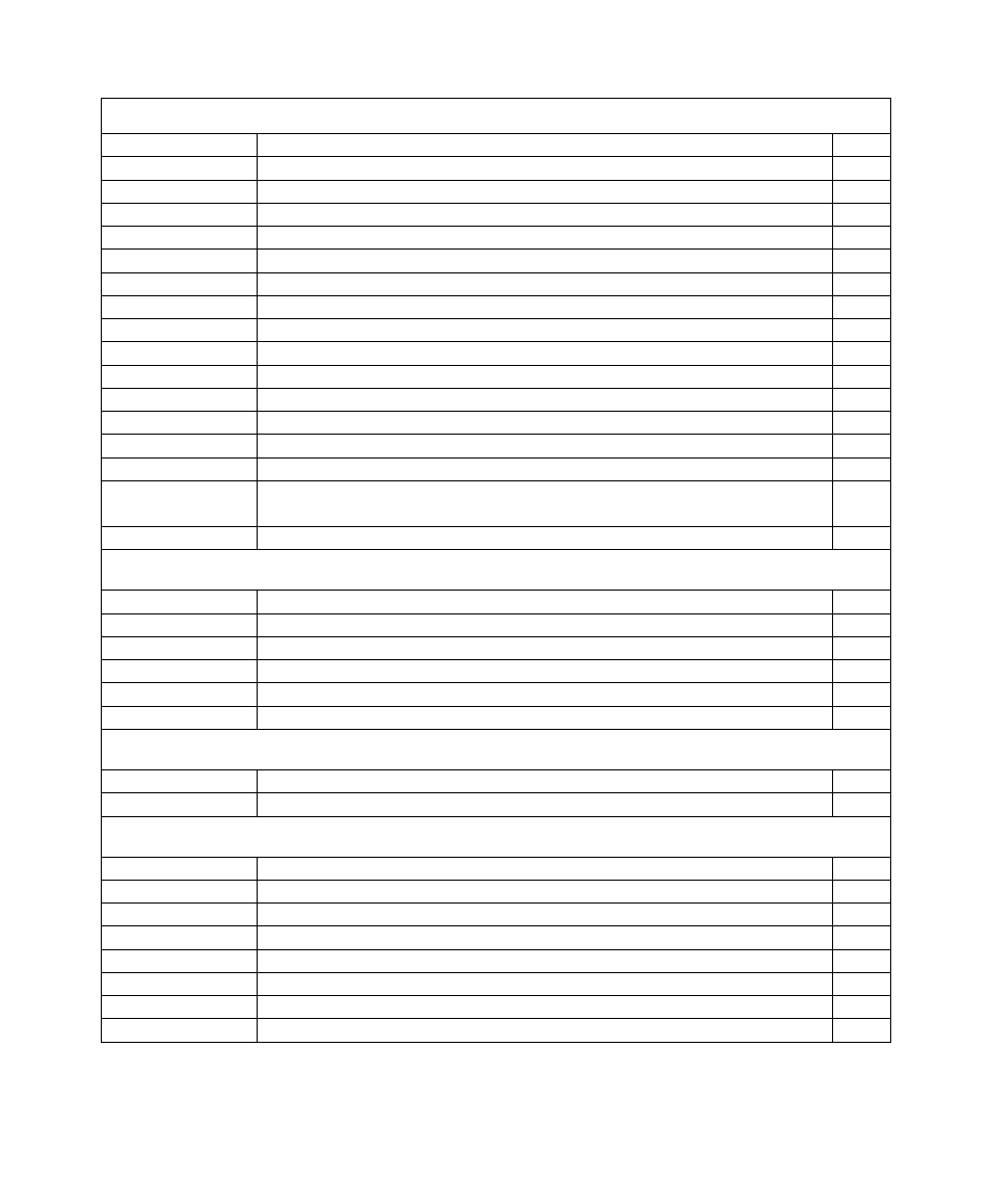
Components on KSB2 Module, continued
R21
Resistor, 68K, 5%, 1/4-watt (blue-gray-orange)
1
R22
Resistor, 560K, 5%, 1/4-watt (green-blue-yellow)
1
R1
Potentiometer, 1 M trimmer ("105")
1
RP3
Resistor network, 2.0 K, 3 R, 6 pins (77063202 or 980663202)
1
RP1,RP2
Resistor network, 2.7 K, 4 R, 8 pins (77083272)
2
RP5
Resistor network, 47K, 5 R, 6 pins (61473)
1
RFC1,RFC2
Toroidal inductor, 19 turns on FT23-43 core (0.23")
2
T1
Toroidal transformer on FT37-43 core (0.375"), 7:22 turns
1
T2
Toroidal transformer on FT37-43 core (0.375"), 4:22 turns
1
U1
IC, Microcontroller, 16F872 or 16F872A
1
U2
IC, Digital-to-analog converter, 8 bits, MAX522
1
U3
IC, Audio amp/speech compressor, SSM2166 (SMD, pre-installed)
1
U4
IC, Dual comparator, LM393
1
U5
IC, Balanced Mixer/Modulator, NE602 (alt: SA602, NE612, etc.)
1
U6
IC, voltage regulator (6 volts), 78L06
1
X1-X7
Crystal, 4.9136 MHz (matched for crystal filter).
Note: Save the envelope, which is labeled with a calibration value.
7
Z1
4.0 MHz ceramic resonator w/internal capacitors
1
Components on Front Panel Board
P1
Conn., dual-row 16p male, 0.1" spcg
1
C4-C8
Capacitor, .01 µF, 0.2" (5 mm) lead spacing
5
Q3
Transistor, PNP, 2N3906
1
RP3
Resistor network, 10 K, 4 R, 8 pins (77083103)
1
Rbias
Resistor, 10 K, 5%, 1/4 W (optional mic bias; see text)
1
R13
Resistor, 68.1K, 1%, 1/4 W
1
Components on RF Board
J11
Conn., 12-pin female, 0.1" pin spcg
1
J9, J10
Conn., 3-pin female, 0.1" pin spcg
2
Hardware and Miscellaneous
HDWR
Socket for U1 on KSB2 module, 28 pins
1
HDWR
#4 split lock washer (quantity shown includes 2 spares)
6
HDWR
4-40 x 1/4" ZN ST phillips machine screw
2
HDWR
Standoff, 3/16" dia. x 3/8" long, round, 4-40 threaded
1
MISC
Wire, #26 enamel, GREEN
2 ft.
MISC
Wire, #28 enamel, RED
5 ft.
MISC
Wire, #24 insulated, solid conductor
2 ft.
MISC
KSB2 PC Board
1