Elecraft KSB2 User Manual
Page 10
10
__R4
(56K, green-blue-orange)
__R20
(18K, brown-gray-orange)
__R21
(68K, blue-gray-orange)
__R22
(560K, green-blue-yellow)
__R23, __R24
(10K, brown-black-orange)
Re-check the values of capacitors CG and CH (39 pF). Once the crystals are installed (following steps)
it is difficult to gain access to these two capacitors.
Locate the envelope containing the matched SSB filter crystals (X1-X7). On the outside of the
envelope you'll find a calibration number that ranges between 3.2 and 3.9. Record the number: ______.
Note: If the envelope is unmarked, use 3.6.
Using the number recorded in the previous step, look up the corresponding LSB and USB transmit
BFO frequencies in the table below. Record these frequencies in Table 3 (page 20) in the two spaces
provided in the BF1t column.
Xtal Cal #
3.2
3.3
3.4
3.5
3.6
3.7
3.8
3.9
LSB
4913.1
4913.2
4913.3
4913.4
4913.5
4913.6
4913.7
4913.8
USB
4915.9
4916.0
4916.1
4916.2
4916.3
4916.4
4916.5
4916.6
Install all 7 crystals, making sure that they are flush with the top of the PC board and are not tilted.
There should be no excess lead length.
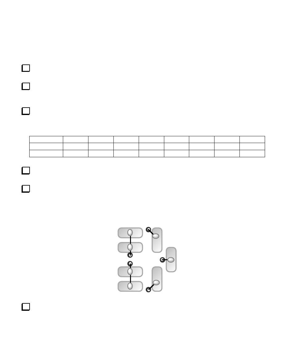
The cases of the crystals should be grounded to the adjacent ground pads using jumpers formed from
discarded component leads. The drawing below shows the ground pads and jumpers as viewed from above
the board. Solder the jumpers to the board first, then fold them over the crystal cans. Be careful not to
overheat the crystal cans when soldering the jumpers in place.
Install 3-pin male connectors P2 and P3 on the bottom of the board. Use the same technique you used
when installing P1. These connectors must not be tilted, and must be seated flush with the board.