Elecraft KSB2 User Manual
Page 14
14
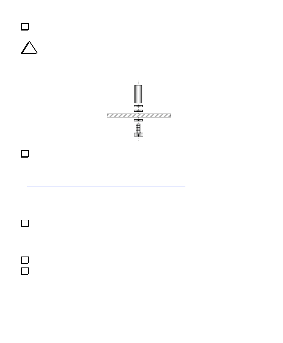
Install the 3/8" (9.5 mm) standoff on the top of the RF board as shown below, using three split lock
washers and a 1/4" (6 mm) machine screw. The hole for the standoff is near the BFO test point (TP2).
i
If you have difficulty getting the screw threads started into the standoff, hold the standoff with
pliers on one side while pushing and turning the screw from the other with a phillips screwdriver. Once the
lock washers start to compress, the screw will mate adequately with the standoff.
If your K2 serial number is 2999 or lower, you should make the 2
nd
XFIL modification to the K2 RF
board at this time. This equalizes the pitch of LSB and USB signals on receive, and provides optimal
sensitivity in all operating modes. (It has no effect on transmit.) The parts for the modification can be
purchased from Elecraft (part #XFILMDKT ). Instructions can be found in this PDF document:
http://www.elecraft.com/Apps/new_fil_docs/k2_2nd_xfil_ssb_mod.pdf
If you don’t have web access, call or write for a printed copy of the instructions.
Note: The modification has already been incorporated into K2's with serial number 3000 and higher. You
may also have made this modification already if you upgraded your K2 to revision B.
Plug the SSB module into the RF board. P1 on the SSB module mates with J11 on the RF board, and
P2-P3 on the SSB module mate with J9-J10. Note that J11 will be obscured by the SSB adapter as you plug
it in, so you won't be able to see whether the pins of P1 are mating correctly. However, if you line up the
pins on P2-P3 with J9-J10, the alignment of P1 and J11 should also be correct. Also look at the hole labeled
"TP2" on the SSB module: you should see the BFO test point centered below this hole.
Secure the SSB adapter to the RF board standoff using a 4-40 screw and one split lock washer.
Re-install the bottom cover (6 screws).