Elecraft KSB2 User Manual
Page 6
6
KSB2 PC Board Assembly
i
A fine-point, temperature-controlled soldering iron (700-800 deg. F, 340-370 deg.
C) is required to assemble this kit, due to the high density of the PC board layout. A high-
wattage iron or one with a wide tip may damage components, pads, or traces. Use a
minimum amount of solder to avoid ground shorts.
i
To avoid difficulties in soldering adjacent components, install components only in
the order described below. Double-check all values before soldering, since removing
small parts from double-sided PC boards can be difficult.
Using the parts list (page 3), identify all of the components that are to be installed on the K2's Front
Panel and RF boards and separate them from the remaining items. Note: The .01 µF capacitors with small
lead spacing (0.1", 2.5 mm) are only used on the KSB2 module, while the .01 µF capacitors with the wider
lead spacing (0.2", 5 mm) will be installed on the Front Panel board.
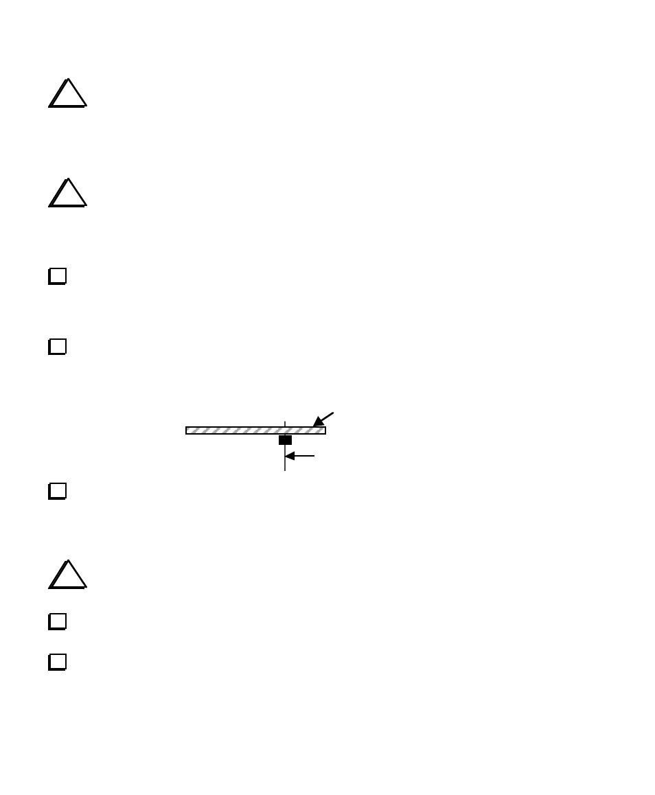
Install 12-pin male connector P1 on the bottom of the PC board in the position indicated by its
component outline. Do not solder yet. The drawing below shows how P1 should appear viewed from the
left end of the board, with the component side up.
P1 (on bottom)
Component side (top)
Solder just one pin of P1 on the top of the board, near the middle of the connector (pin 6 or 7). Verify
that P1 is now perpendicular to the PC board and is seated completely flat. If not, re-heat the soldered pin
and press down on all of P1's pins until the connector drops into place. Once the connector is seated
correctly, solder the remaining pins. This connector must not be tilted or installed at the wrong height.
i
All component leads should be kept short to avoid stray signal coupling. The leads on small
capacitors do not need to be straightened, but keep their mounted height at about 1/8" (3 mm) or less.
Install C30 and C36 (820 pF, "821"), near P1 on the top side of the board. Be careful not to confuse
C30 or C36 with C18, which is farther from P1 and has wider lead spacing.
Install C25 (22 pF, "22" or "220"), which is near the right end of P1 (viewed from the top side).