Troubleshooting, Circuit details, Dc voltage charts – Elecraft KSB2 User Manual
Page 23
23
Troubleshooting
If you have difficulty during test or alignment, do the following:
1. Check the orientation of all ICs, diodes, transistors, electrolytic capacitors and resistor networks.
2. Look for unsoldered pins, solder splashes, or shorts to ground, especially in the area of the crystal filter.
3. Measure resistances to ground in the crystal filter area, checking each crystal, both resistor networks, all diodes,
numbered capacitors, and R5. Leads of these components should show not low resistance to ground.
4.
Do the IC and filter switching diode voltage checks listed below. Be sure to set up the K2 exactly as described.
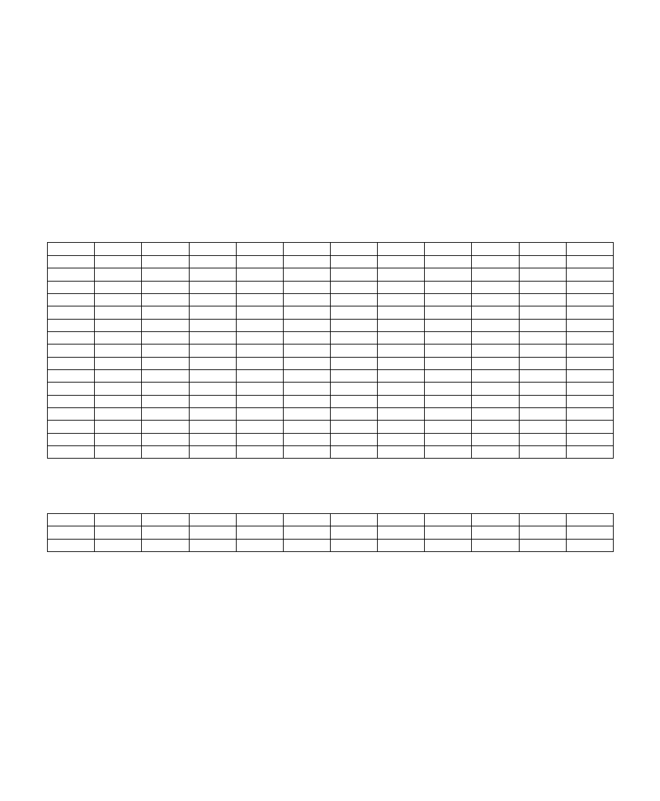
DC Voltage Charts
ICs: Voltages were measured under the following conditions: LSB mode, filter FL1 selected (OP1), VOX = PTT,
POWER set to 0.1W. Menu: SSBA = 3; SSBC = 2-1. Some IC ground pins are not listed.
IC/PIN
RX(V)
TX(V)
IC/PIN
RX(V)
TX(V)
IC/PIN
RX(V)
TX(V)
IC/PIN
RX(V)
TX(V)
U1-1
6.0
6.0
U1-17
6.0
5.6
U2-6
5.6
5.6
U3-14
6.0
6.0
U1-2
5.9
5.3-5.9
U1-18
6.0
6.0
U2-7
6.0
6.0
U4-1
0.0
0.0
U1-3
2.3
2.3
U1-19
0.0
0.0
U2-8
6.0
5.4
U4-2
2.2
2.2
U1-4
0.0
0.0
U1-20
6.0
6.0
U3-1
0.0
0.0
U4-3
0.6
0.6
U1-5
0.0
0.0
U1-21
5.8
0.1
U3-2
0.2
0.2
U4-5
2.2
2.2
U1-6
5.1
0.0
U1-22
0.2
0.0
U3-3
2.5
2.5
U4-6
5.1
0.0
U1-7
0.0
0.0
U1-23
0.0
0.0
U3-4
2.5
2.5
U4-7
0.0
0.0
U1-8
0.0
0.0
U1-24
0.0
0.0
U3-5
2.2
2.2
U4-8
6.0
6.0
U1-9
0.0
2.3
U1-25
0.0
0.8-1.2
U3-6
2.2
2.2
U5-1
0.0
1.4
U1-10
0.0
3.1
U1-26
0.0
0.0
U3-7
1.5
1.5
U5-2
0.0
1.4
U1-11
0.0
0.0
U1-27
0.0
0.0
U3-8
0.36
0.44
U5-4
0.0
3.4
U1-12
0.0
0.0
U1-28
5.6
2.4
U3-9
5.2
5.6
U5-5
0.0
4.8
U1-13
0.0
5.9
U2-1
6.0
5.6
U3-10
0.0
0.0-2.0
U5-6
0.0
5.9
U1-14
6.0
5.9
U2-2
6.0
5.9
U3-11
5.4
5.4
U5-7
0.0
5.1
U1-15
0.0
6.0
U2-3
6.0
6.0
U3-12
0.0
0.0
U5-8
0.0
5.9
U1-16
6.0
5.4
U2-5
0.6
0.6
U3-13
2.3
2.3
Filter Switching Diodes: Voltages were measured at the cathode (banded end) of each diode, in receive mode only.
For CW, use FL = 0.00-2.49 (selects variable bandwidth filter). For SSB, use FL = OP1 (selects fixed SSB filter).
Diode
CW(V)
SSB(V)
Diode
CW(V)
SSB(V)
Diode
CW(V)
SSB(V)
Diode
CW(V)
SSB(V)
D10
5.4
6
D12
6
0
D6
4
6
D8
4.6
1.4
D11
6
0
D13
5.4
6
D7
4.6
1.4
D9
4
6
Circuit Details
RF Circuits: X1-X7 form an optimized, fixed-bandwidth SSB filter. T1 and T2 match the SSB filter's 1500-ohm
input/output impedance to the 150-ohm I.F. path. D6-D13 select either the fixed SSB filter or the CW filter, and also
provide T-R signal routing. D1 sets the overall TX gain via firmware (see Tracking ALC, above), while D2 provides
fast-attack ALC. Q2 and Q3 are emitter followers, buffering the transmit signal on either SSB or CW, respectively.
Audio and Control: Mic audio is amplified and compressed by U3. D-to-A converter U2 controls the ALC threshold
(via Q1), power scaling (D1), and VOX detection threshold (U4). U1 configures the SSB adapter under control of the
K2's main processor, via the 1-wire AuxBus network.