Elecraft KSB2 User Manual
Page 11
11
i
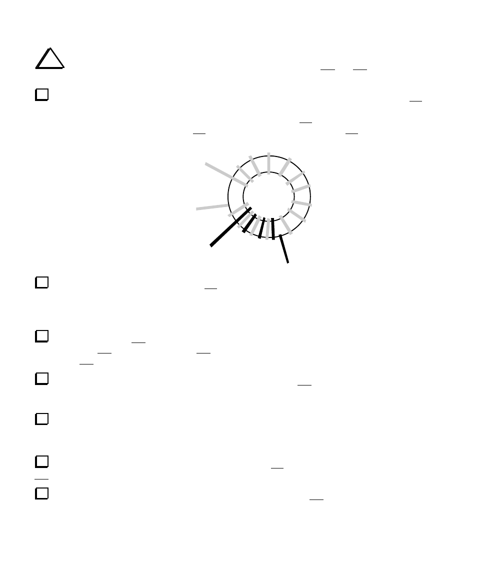
T1 and T2 are toroidal transformers, with two numbered windings: 1–2 and 3–4. These numbers
are printed next to the pads on the PC board, and they also appear on the schematic drawing.
T1 will be wound on a ferrite core (FT37-43, 3/8” [9.5 mm] diameter). For the larger winding, 3-4,
use 22 turns of red enamel wire (13”, 33 cm). This winding will occupy about 80 to 90% of the core, as
shown in the drawing below. (The drawing shows only 14 turns on the 3-4 winding.) Each pass through the
core counts as one turn. Some turns of the 1-2 winding may cross over those of the 3-4 winding.
Green
4
3
1
2
Red
Carefully strip and tin the leads of T1’s 3-4 winding as follows: First, cut the leads to about 1/2" (12
mm) long. Next, completely remove the enamel insulation from the leads to within 1/8” (3 mm) of the core.
You can use a small amount of solder on your iron's tip to heat-strip the insulation (preferred method), or
use a butane lighter or sand-paper. If you scrape the insulation off, be careful not to nick the wire.
T1’s other winding, 1–2, uses 7 turns of green enamel wire (5”, 13 cm). (The drawing shows only 4
turns.) Wind the 1–2 winding on top of the 3–4 winding, using about 20% of the core. Strip and tin the
leads of the 1–2 winding.
Install T1 vertically as shown by its component outline, with the 1–2 winding facing the edge of the
board. Pull the leads taut on the bottom so that the transformer is held firmly in place. Make sure that the
exposed part of each lead is shiny and has no remaining insulation.
Trim and solder all four leads of T1. When soldering, make sure that the solder binds well to the
leads. If the lead appears to be an “island” in a small pool of solder, chances are it is not making good
contact. Measure from leads 1 to 2 and 3 to 4 using an ohmmeter to be sure the leads are making contact.
Wind T2 in the same manner as T1, with 22 turns on the 3-4 winding (red) but only 4 turns on the
1–2 winding (green).
Install T2. It will be rotated 180 degrees with respect to T1, with its 1–2 winding (green) facing the
closest edge of the board.