Dynojet 250iX: Upgrade Installation Guide User Manual
Page 35
M O D E L 2 0 0 I X / 2 5 0 I X U P G R A D E
Monitor Stand and Blowers Installation
Version 1
Model 200iX/250iX Upgrade Installation Guide
1-27
3
Place a 1/4-inch thick poly washer around the pin on the tie-down with the
monitor arm.
4
Place two 1/4-inch thick poly washers around the pin on the tie-down without the
monitor arm.
5
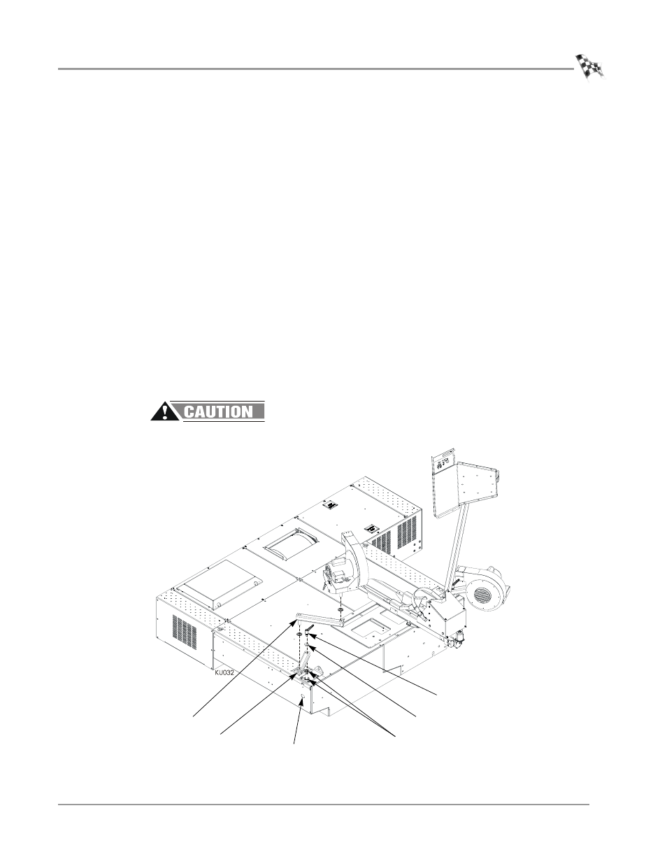
Replace the existing lower blower arms with the new lower blower arms as shown
in Figure 1-23.
6
Place the new lower blower arm over the pin.
7
Place an aluminum washer between the clamp lever and the lower bower arm.
8
Secure the lower blower arm to the tie-down pin using the clamp lever included
in the upgrade.
9
Place a 1/8-inch thick poly washer around the pin on the upper blower arm.
10 Insert the pin on the upper blower arm into the lower blower arm.
11 Place a 1/8-inch thick poly washer around the pin on the blower.
12 Insert the pin on the blower into the upper blower arm.
13 Plug the power cord from the blower into the power source located on the dyno
chassis.
Note: To allow full extension of the right blower, use the blower extension cord
(P/N 76950317). This extension cord is only used with the blower mounted on
the right side of the dyno.
The blowers can run at any time once the cord is plugged into a power source.
Figure 1-23: Installing the Blowers
upper blower arm
1/4-inch thick poly washer
use two on non monitor
arm side
new lower
blower arm
clamp lever
aluminum washer
plug power cord from
blower into dyno chassis