Installing the ix drum module – Dynojet 250iX: Upgrade Installation Guide User Manual
Page 20
Model 200iX/250iX Upgrade Installation Guide
C H A P T E R 1
Drum Installation
1-12
I
NSTALLING
THE
I
X D
RUM
M
ODULE
You will need the following parts:
• 26152030
Spacer
• 36561045
Screw, 1/4-20 x 5/8", PH, Torx (2)
• 37620622
Woodruff Key (2)
• 62240070
Retarder Driveline Assembly
• 63200001
iX Drum Module
1
Remove the drum safety cover from the iX drum module.
2
Remove the six screws securing the iX drum cover and set aside. Remove the
cover and set aside.
3
Place the nylon loop strap around the shaft on either side of the drum module.
4
Using a forklift, lift the drum module from the crate and place the drum module
near the dyno with the stepped end of the shaft towards the dyno. Make sure the
panels on the drum module and the dyno are parallel.
5
Remove the two existing screws (three screws if you have an air pump) from the
dyno frame where the connector plates will attach.
6
Remove the two screws securing the air pump, if present. Refer to Figure 1-8 on
page 1-13.
7
Insert the woodruff key into the keyway on the drum module shaft.
8
Insert the woodruff key into the keyway on the dyno shaft.
9
Slide the driveline over the key on the drum module shaft.
10 Keeping the panels parallel, slide the drum module towards the dyno. Slide the
driveline over the key on the dyno shaft. You will need to support the driveline as
you slide it onto the dyno shaft.
11 Continue sliding the drum module towards the dyno until the side panels on the
drum module and the dyno are flush.
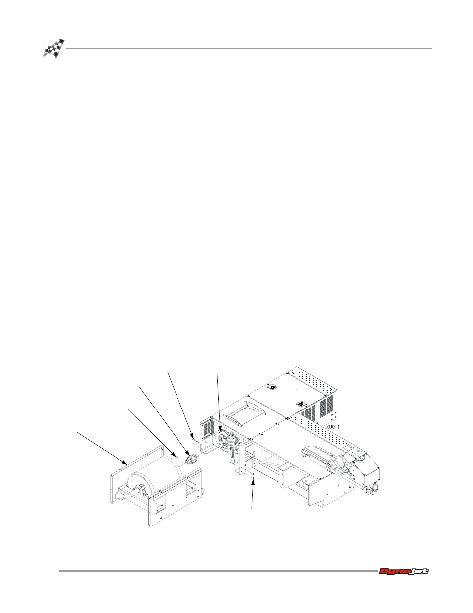
Figure 1-7: Installing the Driveline and the Drum Module
existing screws
iX drum module
driveline
woodruff key
woodruff key
existing screws