Wiring, Wiring -23, Jumper settings – Dynojet 150: Eddy Current Brake User Manual
Page 29
E D D Y C U R R E N T B R A K E I N S T A L L A T I O N
Theta Controller
Version 8
Eddy Current Brake Installation Guide
1-23
W
IRING
1
Remove the four screws securing the Breakout board and cover. Set the cover
aside.
Figure 1-30: Theta Controller—Remove the Breakout Board Cover
2
Attach the temperature cable to the Breakout board. The temperature cable has
five wires which connect to the wiring block labeled TEMP.
3
Attach the control cable to the Breakout board. The control cable has five wires
which connect to the wiring block labeled LOAD CONTROL.
4
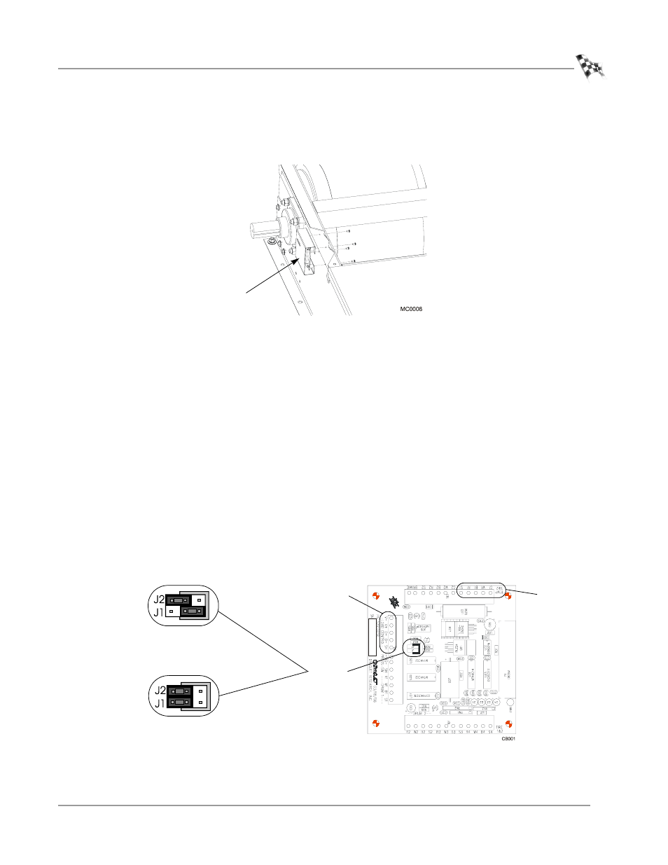
Verify jumpers J1 and J2 are set either for the eddy current brake only or for the
eddy current and air brake as shown in Figure 1-31.
5
Replace the Breakout board cover using the four screws removed earlier.
Figure 1-31: Theta Controller—Breakout Board Wiring and Jumper Settings
• Green wire connects to G1
• White wire connects to W1
• Black wire connects to B1
• Red wire connects to R1
• Ground (shield) wire connects to S1
• Black wire connects to V-
• Red wire connects to V+
• White wire connects to O+
• Green wire connects to O-
• Ground (shield) wire connects to SH
Breakout board
and cover
temp
load control
jumpers
J1 and J2
eddy current brake only
jumper settings
eddy current and air
brake jumper settings