Theta controller, Adjusting the power, Adjusting the power -15 – Dynojet 150: Eddy Current Brake User Manual
Page 21: Figure 1-21: theta controller—metal plug
E D D Y C U R R E N T B R A K E I N S T A L L A T I O N
Theta Controller
Version 8
Eddy Current Brake Installation Guide
1-15
. . . . . . . . . . . . . . . . . . . . . . . . . . . . . . . . . . .
THETA CONTROLLER
This section describes how to install the Theta Controller, make power adjustments,
and replace the fuses.
A
DJUSTING
THE
P
OWER
Newer Theta Controllers are capable of operating at either 60 Hz or 50Hz and are able
to compensate for a lower AC line voltage allowing improved performance under
varying AC power conditions. Each Theta Controller is designed for either the 240
VAC or the 120 VAC range and are not interchangeable. Each eddy current brake is
wired for either 240 VAC or 120 VAC operation and must match the specific Theta
Controller for the desired line voltage.
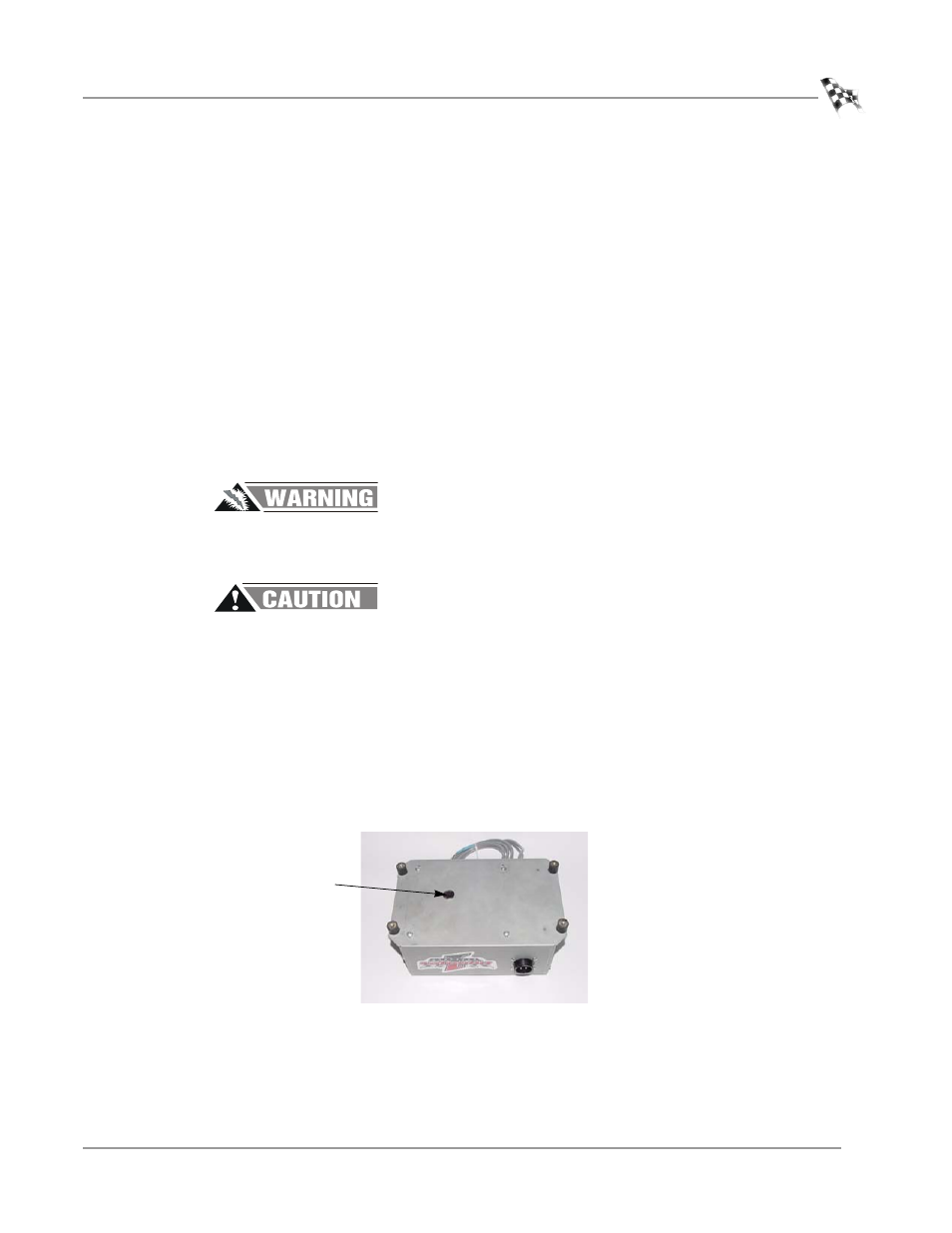
To determine whether a Theta Controller is capable of power adjustments, look for a
metal plug on the bottom of the Theta Controller. Refer to Figure 1-21. If this metal
plug is not present, the Theta Controller is not capable of power line frequency
selection. Continue with the installation instructions.
Hazardous voltage. To avoid risk of electrical shock, disconnect the power cord
to the Theta Controller. Do not remove the cover. No user serviceable parts
inside.
The two dip switches are the only adjustments that can be altered. Be sure not
to damage any other parts on the circuit board. Do not attempt any other
adjustments.
Dynojet recommends you set the dip switches at the time of installation.
1
Remove the metal plug from the bottom of the Theta Controller.
2
Use a small screwdriver to set the dip switches for the desired line voltage.
Refer to “120 VAC Theta Controller (P/N 66411002)” on page 1-16 and “240 VAC
Theta Controller (P/N 66411003)” on page 1-17 for more information on dip
switch settings.
3
Replace the metal plug.
Figure 1-21: Theta Controller—Metal Plug
metal plug