Eddy current brake, Adjusting the brake for right side installations, Installing the connecting arms – Dynojet 150: Eddy Current Brake User Manual
Page 15: Figure 1-11: right side installation set-up, Figure 1-12: remove the connecting arm bolts
E D D Y C U R R E N T B R A K E I N S T A L L A T I O N
Eddy Current Brake
Version 8
Eddy Current Brake Installation Guide
1-9
. . . . . . . . . . . . . . . . . . . . . . . . . . . . . . . . . . .
EDDY CURRENT BRAKE
The eddy current brake can be installed on either the left or right side of the dyno. Be
sure to check the dyno drum axle for damage or rust and carefully file any marks flush
with the axle.
A
DJUSTING
THE
B
RAKE
FOR
R
IGHT
S
IDE
I
NSTALLATIONS
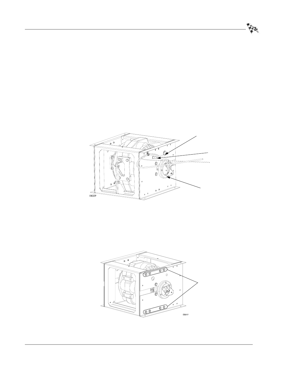
Make the following adjustments to the eddy current brake only if the brake will be
mounted on the right side of the dyno.
1
Move the coupler and key to the other side of the brake.
2
Move the sensor temperature cable and power cable to the other side of the
brake.
Figure 1-11: Right Side Installation Set-up
I
NSTALLING
THE
C
ONNECTING
A
RMS
Attach the upper and lower connecting arms on the corresponding side of the eddy
current brake. The connecting arms are identical and interchangeable.
1
Remove the eight 3/8-inch bolts and washers from the side of the eddy current
brake.
Figure 1-12: Remove the Connecting Arm Bolts
power cable
temp sensor cable
coupler
remove