Dynojet 150: Eddy Current Brake User Manual
Page 27
E D D Y C U R R E N T B R A K E I N S T A L L A T I O N
Theta Controller
Version 8
Eddy Current Brake Installation Guide
1-21
5
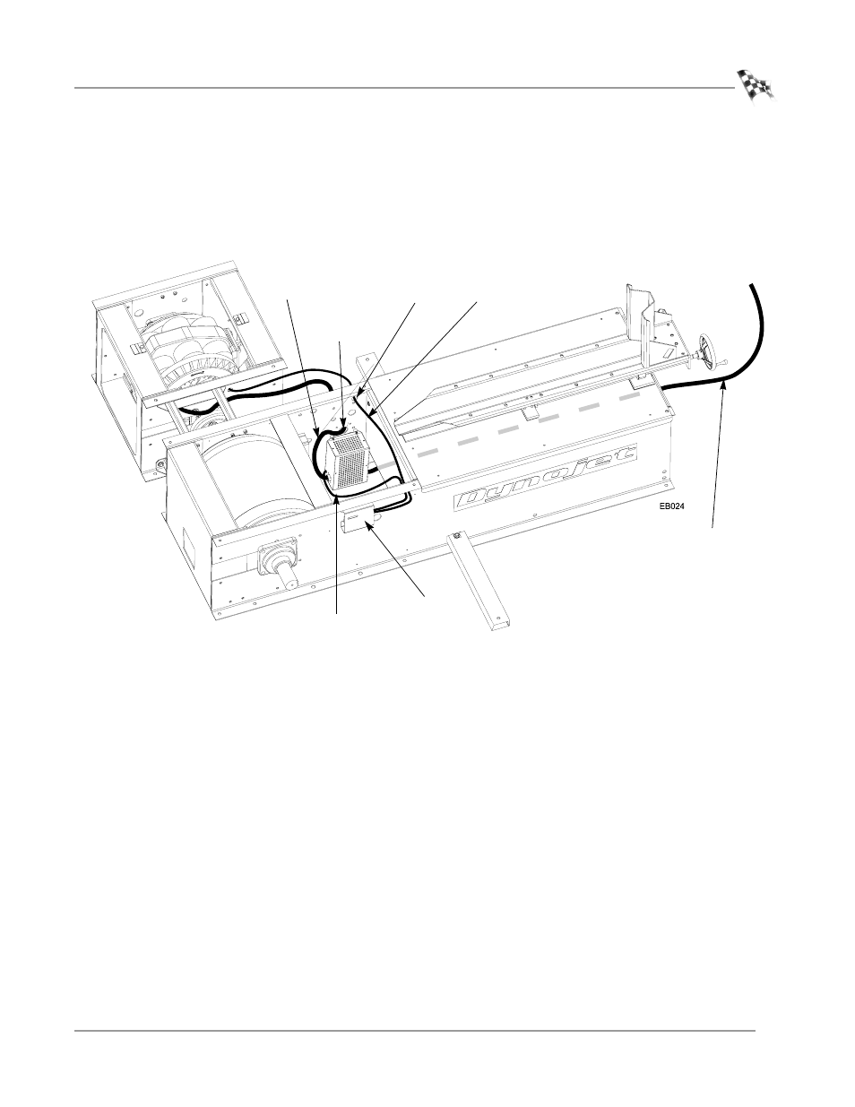
Route the input power cable under and out the front of the dyno.
6
Insert the smaller rubber grommet as shown in Figure 1-27.
7
Route the temperature sensor cable from the eddy current brake through the
dyno to the Breakout board.
8
Route the control cable from the Theta Controller to the Breakout board.
Figure 1-27: Theta Controller—Routing the Cables on Left Side
temp sensor
cable
brake power
cable
control cable
input power
cable
Breakout board
small
grommet
large
grommet
This manual is related to the following products:
See also other documents in the category Dynojet Equipment:
- 150: Kart and ATV Dynamometers (44 pages)
- 150: Dyno Drum Cover for Kart and ATV Dyno Motorcycle Option (3 pages)
- 150: WinPEP 7 (170 pages)
- 168: Eddy Current Brake (27 pages)
- 200: Replacing the Starter Ring Gear (7 pages)
- 200: Safety Switch (3 pages)
- 200: DynoWare EX+ Upgrade Installation Guide for Motorcycle Dynos (20 pages)
- 200: Throttle Stop (3 pages)
- 200: Eddy Current Brake Driveline Upgrade (17 pages)
- 200i: High Pressure Blower (20 pages)
- 200: Installation Guide (73 pages)
- 200i: Pit Installation Guide (154 pages)
- 200i: Pre-Installation Guide (52 pages)
- 200i: Installation Guide (184 pages)
- 200i: Air Brake and EEC Kit (40 pages)
- 200i: Dynamometer Wiring Schematic (2 pages)
- 200i: Folding Ramp (15 pages)
- 200i: Control Panel Interface Upgrade (S/N 201xxxx) (31 pages)
- 200i: Control Panel Interface Upgrade (S/N 202xxxx) (29 pages)
- 200i: Motorcycle Exhaust Extraction System Drawings (18 pages)
- 200iP: Pit Installation Guide (148 pages)
- 200iPX: Installation Guide (52 pages)
- 200iPX: Installation Guide (163 pages)
- 200ix: Pit Installation Guide (163 pages)
- 200ix: Extended Carriage and Trike Adapter Assembly (15 pages)
- 200iX: Upgrade Installation Guide (56 pages)
- 200ix: Extended Carriage with Trike Adapter Assembly (13 pages)
- 224: CE Package (17 pages)
- 224: Maintenance Guide (35 pages)
- 224: Installation Guide (78 pages)
- 224/4WD: Installation Guide (77 pages)
- 224: Pit Installation Guide (56 pages)
- 224x: Above Ground Four Post Lift Dimensions (1 page)
- 224x: Pre-Installation Guide (63 pages)
- 224x: 4WD Dyno Air and Wiring Schematic (2 pages)
- 224: Eddy Current Brake (73 pages)
- 224: Pit Eddy Current Brake (69 pages)
- 224xLC2: Quickstart guide for DWRT (2 pages)
- 248: Pit Installation Guide (74 pages)
- 248: Installation Guide (58 pages)
- 248: DynoTRAC User Guide with Variable Brake (14 pages)
- 248: DynoWare EX+ Upgrade (22 pages)
- 248: Optical RPM Sensor (22 pages)
- 248: Proportional Air Brake (21 pages)