Dip switch settings – Dynojet 150: Eddy Current Brake User Manual
Page 22
Eddy Current Brake Installation Guide
C H A P T E R 1
Theta Controller
1-16
120 VAC T
HETA
C
ONTROLLER
(P/N 66411002)
The 120 VAC Theta Controller is designed for operation in North America and Japan
and is identified by a single external fuse holder. This controller is nominally
calibrated for 115 to 120 VAC line voltage; in Japan, the nominal line voltage is 100
VAC and the dip switch on the Theta Controller can be set to compensate for the
reduced line voltage while still providing the full output current of 20 amps.
Note: This controller cannot be converted to operate on 240 VAC line voltage.
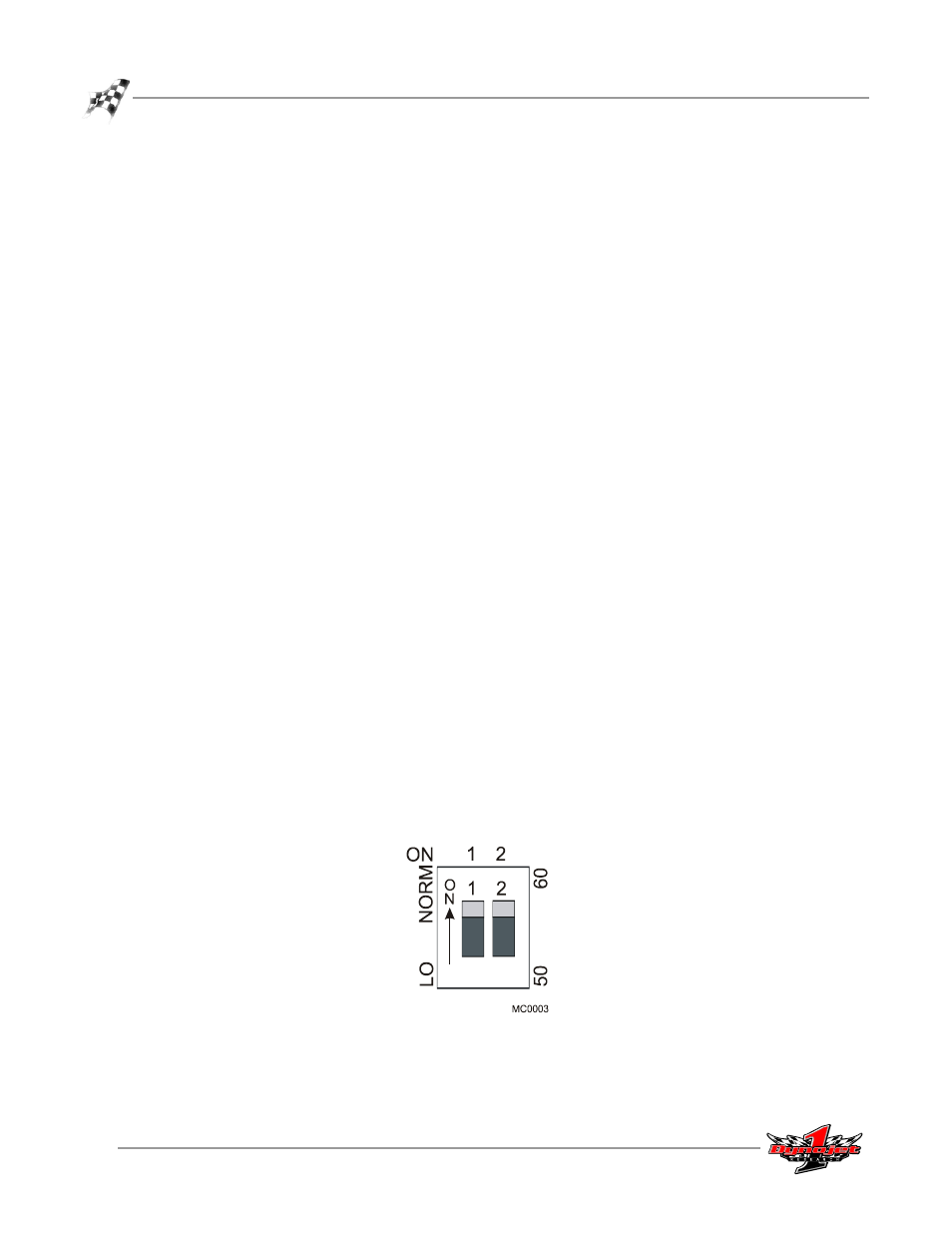
Power Line Frequency Adjustment—The Theta Controller is shipped with the dip
switch set for 60 Hz. For all of North America, this switch should be set to the 60 Hz
position. In Japan, there may be either 50 Hz or 60 Hz power line frequency;
determine the correct line frequency and set the switch accordingly.
Power Line Voltage Adjustment—The Theta Controller is shipped with the dip
switch set for normal (NORM) line voltage. In the NORM position, the controller is
calibrated for a nominal 115 to 120 VAC line voltage. For all of North America, this
switch should be set to the NORM position. In Japan, the nominal line voltage is rated
for 100 VAC and the dip switch should be set to the LO position.
In some cases in North America, it may be necessary to set the dip switch to the LO
position when the AC line voltage is consistently around or below 110 VAC and
combined with reduced brake performance.
• Measure the AC line voltage with all normal AC loads running in the shop (lights,
heater, etc.).
• If the line voltage is reduced to or below 110 VAC and remains at these levels, move
the switch to the LO position. This will boost the output current with the lower AC
power voltages.
Note: Be sure to review and comply with the model 250 motorcycle dyno
installation requirements before setting the dip switch to the LO position. The
Theta Controller should be on its own dedicated AC power circuit.
Note: If the AC power voltage returns above the 115 VAC range while the dip
switch is set to LO, overheating and damage to the eddy current brake or fuse
failure may result. Review the LO/NORM dip switch position setting and re-
measure your incoming AC line voltage.
Figure 1-22: Theta Controller—North America 120 VAC Dip Switch Settings