Write operation, Bit data-width mode, Figure 5: 32-bit data width sbus write operation – Achronix Speedster22i sBus User Manual
Page 13: Sbus interfaces, Chapter_3
UG047, October 24, 2013
13
Write Operation
32-bit Data-width Mode
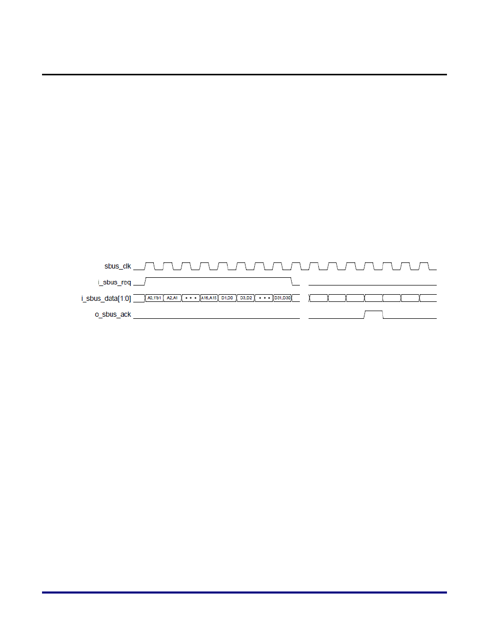
For a 32-bit data-width mode write operation, you must do the following.
1. Assert the i_sbus_req signal for 25 cycles.
2. Assert i_sbus_data[0] during the first cycle.
3. Send the LSB of the 17-bit long write address on i_sbus_data[1] during the first cycle.
4. Send the remaining 16 bits of the read address on i_sbus_data[1:0] in the following order
[A2:A1]…[A16:A15] over the next 8 cycles.
5. Send the 32-bit data on i_sbus_data[1:0] in the following order [D1:D0]…[D31:D30].
6. De-assert i_sbus_req signal.
The sBus slave will decode and complete the write operation and respond as follows.
7. Assert the o_sbus_ack signal to indicate the end of the write operation.
Figure 5 shows the timing diagram for a 32-bit data width, sBus write operation.
Figure 5: 32-bit Data Width sBus Write Operation
8-bit Data-width Mode
For an 8-bit data-width mode write operation, you must do the following.
1. Assert the i_sbus_req signal for 13 cycles.
2. Assert i_sbus_data[0] during the first cycle.
3. Send the LSB of the 17-bit long write address on i_sbus_data[1] during the first cycle.
4. Send the remaining 16 bits of the read address on i_sbus_data[1:0] in the following order
[A2:A1]…[A16:A15] over the next 8 cycles.
5. Send the 8-bit data on i_sbus_data[1:0] in the following order [D1:D0]…[D7:D6].
6. De-assert i_sbus_req signal.
The sBus slave will decode and complete the write operation and respond as follows.
7. Assert the o_sbus_ack signal to indicate the end of the write operation.
Figure 6 shows the timing diagram for an 8-bit data width, sBus write operation.