Figure 12: read interface 2x clock mode – Achronix Speedster22i DDR User Manual
Page 24
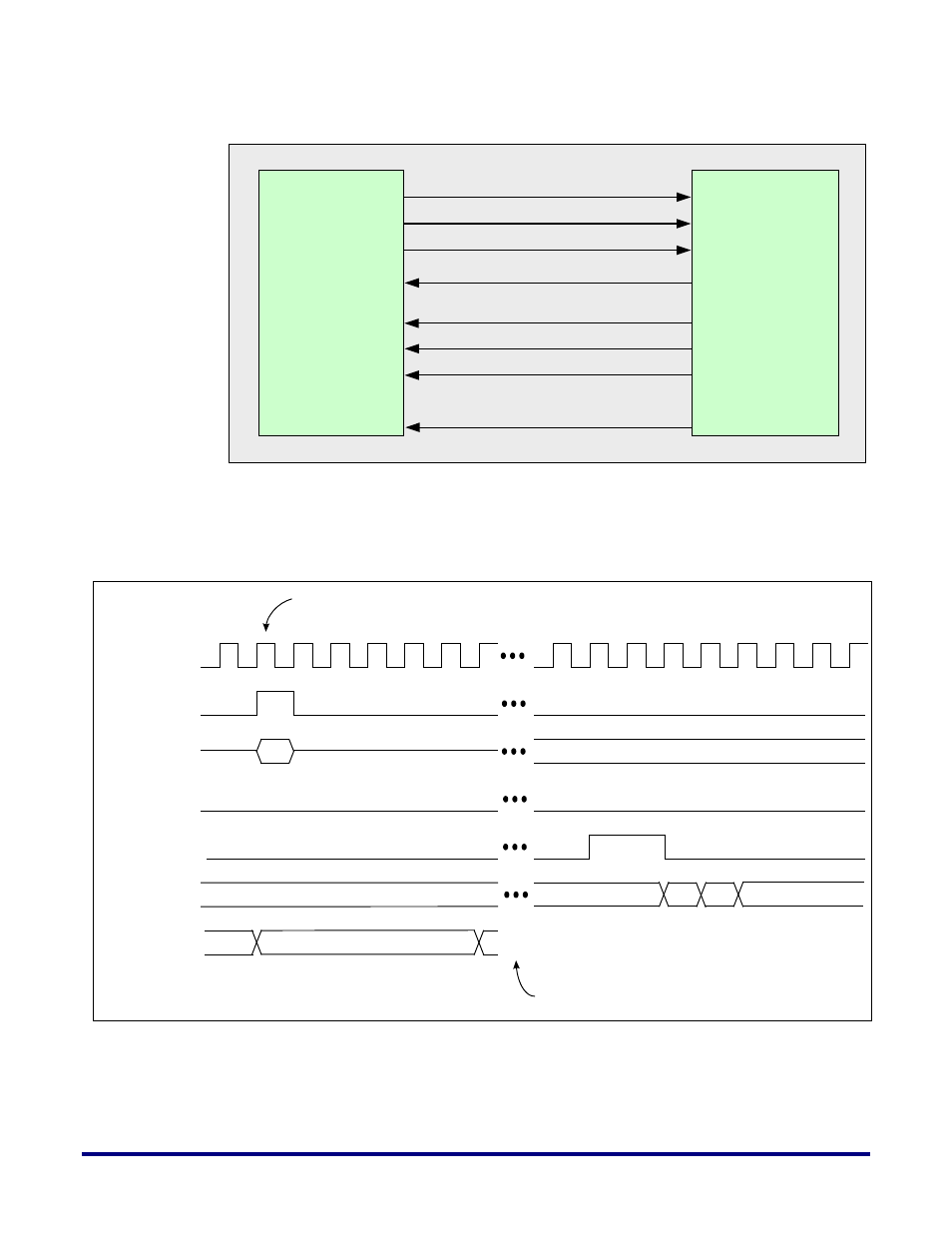
Figure 12: Read Interface 2X Clock Mode
The following timing diagram illustrates a single read command of burst length 4. The
signals shown in the following diagrams are ports at the (‘ddr3_xSIZE
1
_LOCATION
2
’. Where
1: SIZE = 72, 64, 32, 16, 8 and 2: LOCATION=EN, EC, ES, WN, WC, WS).
Figure 13: Internal Interface Read Protocol Timing Diagram
ddr_int_rd_request
ddr_int_busy_align
ddr_int_addr[33:0]
ddr_int_rddata_valid_align
ddr_int_rddata[287:0]
Speedster22i
DDR
Controller
DDR Driver
Logic
(in Core Fabric)
ddr_int_burst_size[7:0]
ddr_int_rddata_valid_early_align
clk_div2
clk_div2
ddr_int_rd_ request
a 0
ddr_int_ addr[33:0]
ddr_int_ busy_ align
d0
d1
ddr_int_ rddata_ valid_ align
ddr_int_ rddata[ 287:0]
Valid Read Command
4
ddr_int_ burst_size[7:0]
Timing relationship between ddr_int_rd_request and
ddr_int_rddata_valid assertion based on AL/CL configuration
settings, refresh status and status of bank/row begins assessed
24
UG031, Nov 18, 2014