Back-to-back write protocol 2x clock mode – Achronix Speedster22i DDR User Manual
Page 19
Back-to-Back Write Protocol 2X Clock Mode
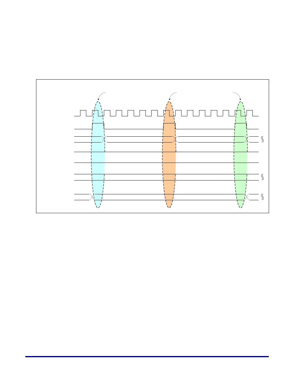
The following timing diagram (Figure 8) illustrates the same three cascaded, back-to-back
write commands. Each valid write request (and corresponding data) is highlighted in a
different color. For back-to-back write there are 5 clock-cycles gap required between the write
requests. This is done with respect to 2X clock mode.
Figure 8: Write Protocol Timing Diagram (Write requests with valid writes highlighted)
a0
a1
a2
Valid Write commands after 5 cycles
clk_div2
ddr_int_wr_request
ddr_int_addr[33:0]
ddr_int_busy
ddr_int_wrdata_req
ddr_int_burst_size [7:0]
...
...
...
...
4
ddr_int_wrdata [287:0]
UG031, Nov 18, 2014
19