Register interface – Achronix Speedster22i Interlaken User Manual
Page 36
Register Interface
The register interface provides access to control and status registers for the IIPC. These registers
can be accessed via the FPGA’s SBus. IIPC is a slave on SBus. Users need to design the master
interface in the fabric to drive SBus. For information about the SBus, see
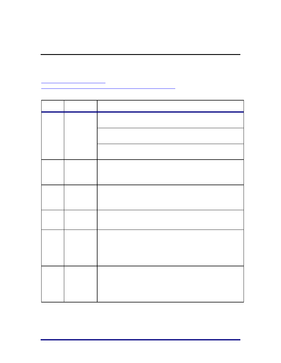
Address
Name
Description
0x0102
txdecomm
TX Decommissioning Register – R/W – Default: ‘h1717
Bits 4:0 – TX Last Lane (ctl_tx_last_lane)
Bits 12:8 TX Bad Lane (ctl_tx_has_bad_lane)
0x0104
txlanestat
TX Lane Status Messaging Register – R/W
Setting Bit X to 1 sets Bit 33 in the Diagnostic Word for lane X
(ctl_tx_diagword_lanestat)
0x0108
txintfstat
TX Interface Status Messaging Register – R/W
Setting bit 0 to a value of 1 sets bit 32 in the Diagnostic Word for each
lane (ctl_tx_diagword_intfstat)
0x010A
txrlimen
TX Rate Limiter Enable Register – R/W
Setting bit 0 to a value of 1 enables the rate limiter. (ctl_tx_rlim_en)
0x010C
txrlimmax
TX Rate Limiter Max Tokens Register – R/W
Bits 11:0 specify how many tokens are to be added to the token
bucket after each interval. This value must be greater than 0. This
value should not be changed when the rate limiter is enabled.
(ctl_tx_rlim_max)
0x010E
txrlimdelta
TX Rate Limiter Delta Register – R/W
Setting bits 11:0 specifies how many tokens are to be added to the
token bucket after each interval. This value must be greater than 0.
This value should not be changed when the rate limiter is enabled.
(ctl_tx_rlim_delta)
UG032, May 15, 2014
36