Achronix Speedster22i Interlaken User Manual
Page 16
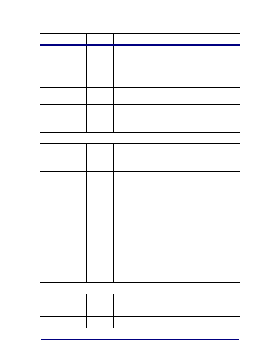
Name
Direction
Clock
Description
corresponding bit of this bus.
rx_serdes_resetn[11:
0]
Input
Reset for each RX SerDes lane. The
recovered clock for each SerDes lane has
associated with it an active-low reset. This
signal is low until transmit and receive
data-paths of each SerDes are ready.
tx_serdes_refclk
Input
Common clock for the all Tx SerDes
interfaces.
tx_serdes_refclk_res
etn
Input
Active low reset for TX Reference clock.
This signal is low until the PLL in the
SerDes is locked and the transmit data-path
is ready in lane #0.
LBUS Interface – Clock/Reset Signals
clk
Input
Local bus clock. All signals between the
IIPC and the user side logic are
synchronized to the positive edge of this
signal.
rx_resetn
Input
Asynchronous reset for the RX circuits.
This signal is active low (0 = reset). Initially
this reset is applied from the board.
Subsequently it can be applied by the user
dynamically or based on the readiness of
SerDes receive and transmit paths. The
IIPC handles synchronizing the rx_resetn
input to the appropriate clock domains
within the IIPC.
tx_resetn
Input
Asynchronous reset for the TX circuits. This
signal is active low (0 = reset). Initially this
reset is applied from the board.
Subsequently it can be applied by the user
dynamically or based on the readiness of
SerDes PLL and transmit path. The IIPC
handles synchronizing the tx_resetn input
to the appropriate clock domains within the
IIPC.
LBUS Interface – RX Path Signals
rx_dataout[511:0]
Output
clk
Receive LBUS Data. The value of the bus is
only valid in cycles that rx_enaout is
sampled as 1.
rx_chanout[7:0]
Output
clk
Receive Channel Number. The bus
UG032, May 15, 2014
16