Caution, Fig. 4 fig. 5, Fig. 6 fig. 7 – Qmark CP - Radiant Ceiling Panels User Manual
Page 3: Fig. 8
SURFACE MOUNTING
1. The Surface Mounting Kit comes a in separate carton which
contain two side frames, two end frames, and eight assem-
bly screws.
2. Assemble the end frames to the side frames using the
screws provided (see Fig. 4) before installing on the ceiling.
3. Mounting the frame assembly to the ceiling.
4. Remove one end frame and install heater panel in side
frames as shown in Fig. 5.
5. Connect the heater panel leads to the power supply leads
(see Fig. 3 and WIRING instructions). The heater must be
properly grounded as a precaution against electrical shock.
Use a properly grounded junction box for connecting the
heater to the power supply. The heater may be moved along
side frames to facilitate wiring.
6. Re-assemble the end frame to the side frames to lock the
heater panel securely in place.
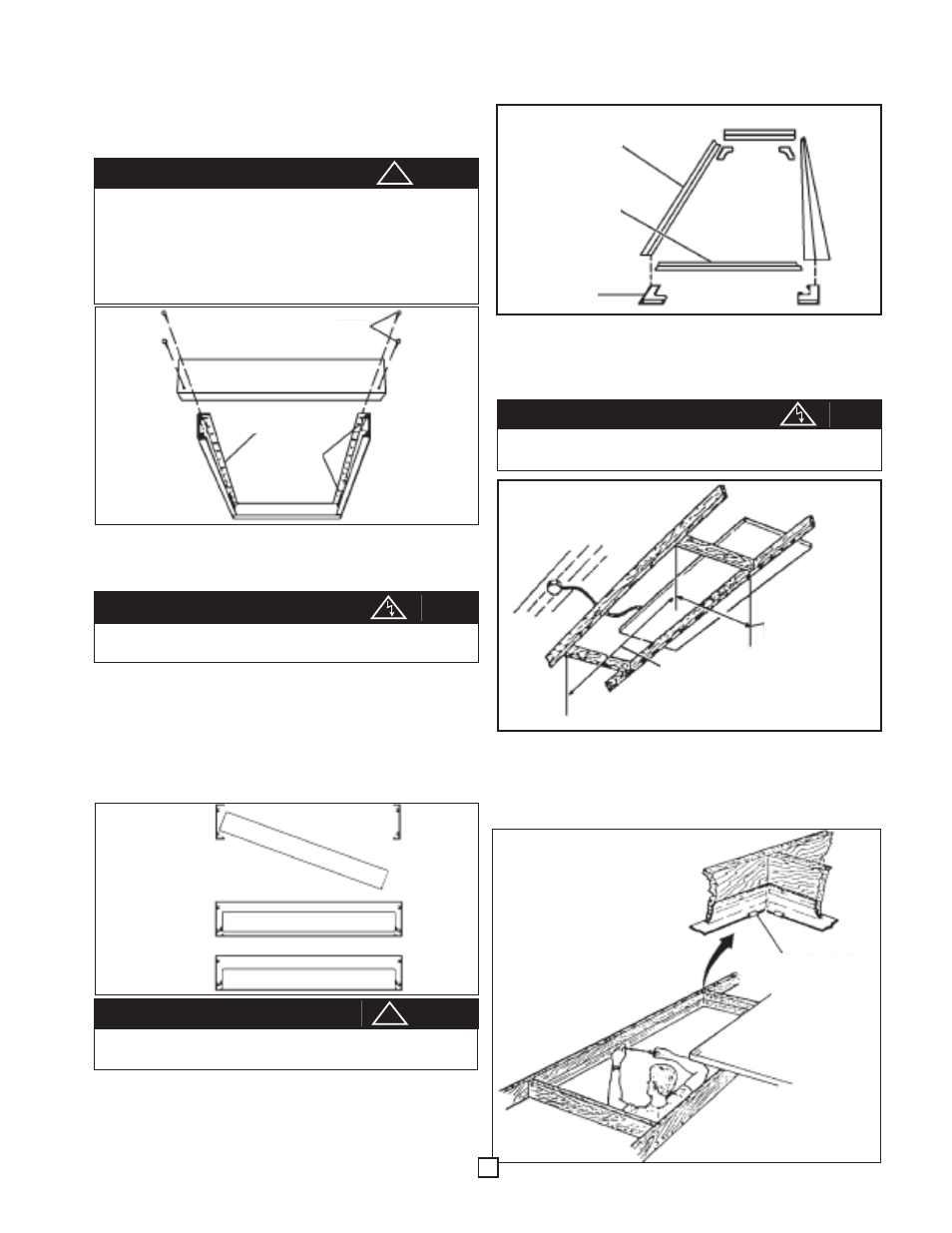
RECESS MOUNTING
1. The Recess Mounting Kit comes in a separate carton which
contain four frame sections and four corners (See Fig. 6).
2. Recessed heater panels require a cutaway in ceiling and a
secure method of support (see Fig. 7). Use boards no
smaller than 2"x 4" (5cm x 10cm) for support. Use screws
no smaller than number 10 in each hole provided in side and
end frames.
3. Insert the heater panel through the opening (see Fig. 7) and
make wiring connections (see Fig. 3 and WIRING instruc-
tions). The heater must be properly grounded as a precau-
tion against electrical shock. Use a properly grounded junc-
tion box for connecting the heater to the power supply.
4. Loosely screw side and end frames to ceiling opening, then
attach corners in place (see Fig. 8).
5. After attaching corners, tighten screws securely.
6. Carefully lower heater panel in place on frames.
To prevent possible injury from falling panels, use at
least four screws (1/4" or 0.635 minimum diameter) to
secure each side frame. Screws must thread securely
into a sturdy structural member of the ceiling, such as a
ceiling joist. It may be necessary to frame-in an extra
support member. Do not finish from dry-wall, plater or
other finish ceiling materials.
CAUTION
Be sure electricity is turned off at main switch before
wiring to prevent possible injury from electric shock.
CAUTION
Failure to mount this kit securely may result in serious
personal injury from falling heat panels.
CAUTION
Fig. 4
Fig. 5
A
Be sure electricity is turned off at main switch before
wiring to prevent possible injury from electric shock.
CAUTION
Fig. 6
Fig. 7
!
!
Fig. 8
3
SIDE FRAME
END FRAME
CORNER
END FRAME
SCREWS
SIDE FRAME
MOUNTING
HOLES
Step A
Step B
Panel
length
plus 3/8”
(9.5 mm)
Panel width plus
3/8” (9.5 mm)
(ALL DIMENSIONS
ARE INSIDE)
PLACE CORNER
IN POSITION AND
SECURE BY
BENDING TABS UP
Step C