Caution, Fig. 2 fig. 1, Fig. 3 – Qmark CP - Radiant Ceiling Panels User Manual
Page 2
NOTE: For a period of time after the panels are put into
operation the owner may notice a “new smell” coming
from the heaters. This is expected on new installations
and will dissipate after approximately 24 hours of opera-
tion.
PAINTING
1. Heaters may be repainted. Do not remove paint from
heaters. The surface must be first free of grease or
oil. Use only a thin brush-on coat of high quality pure
acrylic water base flat latex. An off-white will give better
coverage.
Do not paint with aluminum, oil base, vinyl-latex or
rubber-base latex paint.
T-BAR MOUNTING
1. The heater panels are designed for installation in T-Bar
ceilings.
2. Three (3) inch (7.67cm) minimum distance must be pro-
vided between the front painted surface and the ceiling
above. However, installation may be difficult and six (6)
inches (15.2 cm) or more clearance will improve instal-
lation of heaters and inspection or wiring. It may be nec-
essary to remove a cross tee for installation when T-Bars
are at close distances to the ceiling.
3. Locate T-Bar hanger wires at the corners where the
cross tees intersect the main tees so that they do not
interfere with installation or removal of panels.
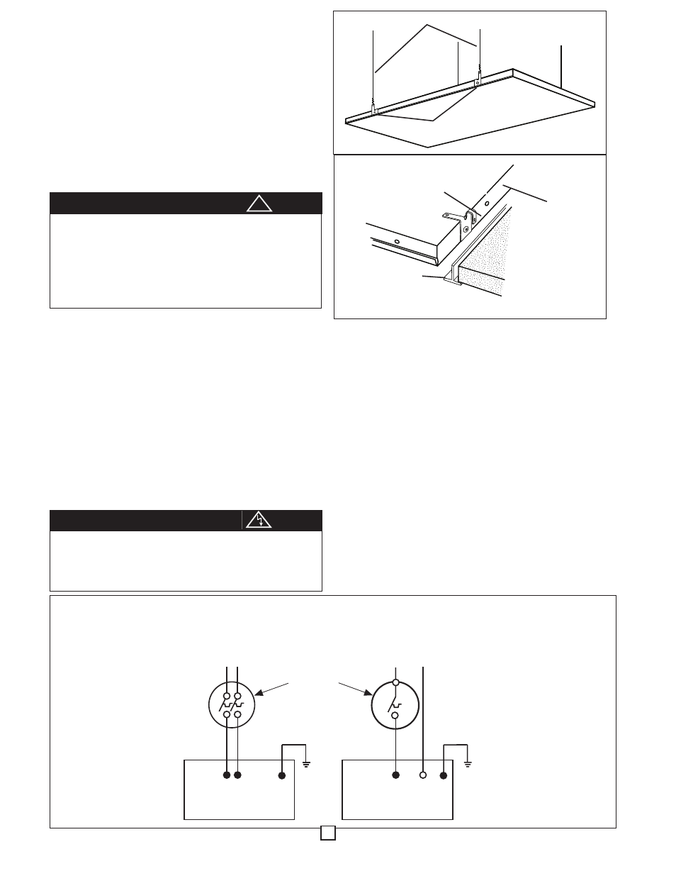
4. The heater panels are supplied with four built in hang-
ing/hold-down clips which are located on each long side of
the heater panel. The clips can be used either to hang the
heater with support wires (see Figure 1) or bent as hold
down clips to the T-Bar frame (see Figure 2). Carefully lift
heater panel into place, making sure hold down clips hook
securely over T-bar (see Figure 2).
WIRING
1. Maximum number of heaters per circuit is limited to cir-
cuit wiring and thermostat or switch capacity. See cata-
log for available thermostats and Warning No. 2.
2. Make wiring connections in accordance with Fig. 3 (on
following page) and wiring instructions. The heater must
be properly grounded as a precaution against electrical
shock. Use a properly grounded junction box for con-
necting the heater to the power supply.
3. Always use a properly grounded junction box when
splicing. See wiring diagrams for proper connections.
Install only in a location where the power supply con-
nections will be accessible. Install junction box as far
above panel as possible and above building insulation,
where present. Use field wiring suitable for 90 ºC if
junction box is allowed to lie on heater or is enclosed
between heater and ceiling above. When installed in a
drop ceiling, the wiring terminals should be accessible
through removable ceiling sections with adequate clear-
ance to permit access to the top of the heater.
To prevent possible injury from falling panels, the T-Bar
must be securely fastened to the building structure and
capable of supporting the weight of the panel (30
pounds). Extra holes are provided for suspending the
heater panel (see Fig. 1) on steel wires no smaller than
No. 18 ga. (0.047 in. diameter / 0.119 cm diameter).
These extra support wires must be used where T-Bar
strength is inadequate or where vibration is anticipated.
CAUTION
To prevent possible injury from electric shock, make
sure that electricity is turned off at the main switch. All
wiring must be done in accordance with national and
local codes and the unit must be properly grounded as
a precaution against electrical shock.
CAUTION
Fig. 2
Fig. 1
!
BLACK BLACK
G
208 OR 240 VOLT
HEATER
LINE VOLTAGE
THERMOSTAT
OR SWITCH
(NOT INCLUDED)
SEE NAMEPLATE FOR
LINE VOLTAGE SUPPLY
WIRING
DIAGRAM
HEATERS MUST BE
PROPERLY GROUNDED
BLACK WHITE
G
120, 277 OR 347 VOLT
HEATER
SEE NAMEPLATE FOR
LINE VOLTAGE SUPPLY
Fig. 3
2
HOLD DOWN CLIP
SUPPORT WIRES
HOLD DOWN CLIPS
T-BAR
HEATER
PANEL