Video connector, Usb connector – Dell PowerEdge 1750 User Manual
Page 8
The PS/2-compatible keyboard and mouse cables attach to 6-pin, miniature DIN connectors.
illustrates the pin numbers for these connectors and
defines the pin assignments for these connectors.
Figure B-4. PS/2-Compatible Keyboard and Mouse Connector Pin Numbers
Table B-3. Keyboard and Mouse Connector
Pin Assignments
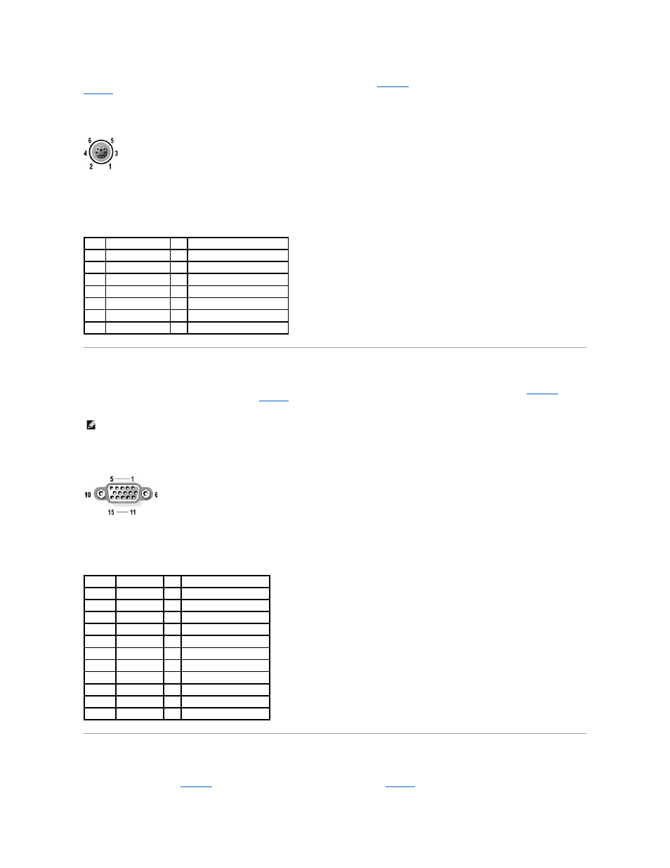
Video Connector
You can attach a VGA-compatible monitor to the system's integrated video controller using a 15-pin high-density D-subminiature connector.
illustrates the pin numbers for the video connector and
defines the pin assignments for the connector.
Figure B-5. Video Connector Pin Numbers
Table B-4. Video Connector Pin Assignments
USB Connector
The system's USB connector supports USB-compliant peripherals such as keyboards, mice, and printers and may also support USB-compliant devices such as
diskette drives and CD drives.
illustrates the pin numbers for the USB connector and
defines the pin assignments for the connector.
Pin
Signal
I/O Definition
1
KBDATA or MSDATA I/O Keyboard data or mouse data
2
NC
N/A No connection
3
GND
N/A Signal ground
4
FVcc
N/A Fused supply voltage
5
KBCLK or MSCLK
I/O Keyboard clock or mouse clock
6
NC
N/A No connection
Shell N/A
N/A Chassis ground
NOTE:
Installing a video card automatically disables the system's integrated video controller.
Pin
Signal
I/O Definition
1
RED
O
Red video
2
GREEN
O
Green video
3
BLUE
O
Blue video
4
NC
N/A No connection
5–8, 10 GND
N/A Signal ground
9
VCC
N/A Vcc
11
NC
N/A No connection
12
DDC data out O
Monitor detect data
13
HSYNC
O
Horizontal synchronization
14
VSYNC
O
Vertical synchronization
15
DDC clock out O
Monitor detect clock