Rac ethernet connector, Integrated nic connector, Figure b – Dell PowerEdge 1750 User Manual
Page 9: Table b, Defines the pin assignments for the connector
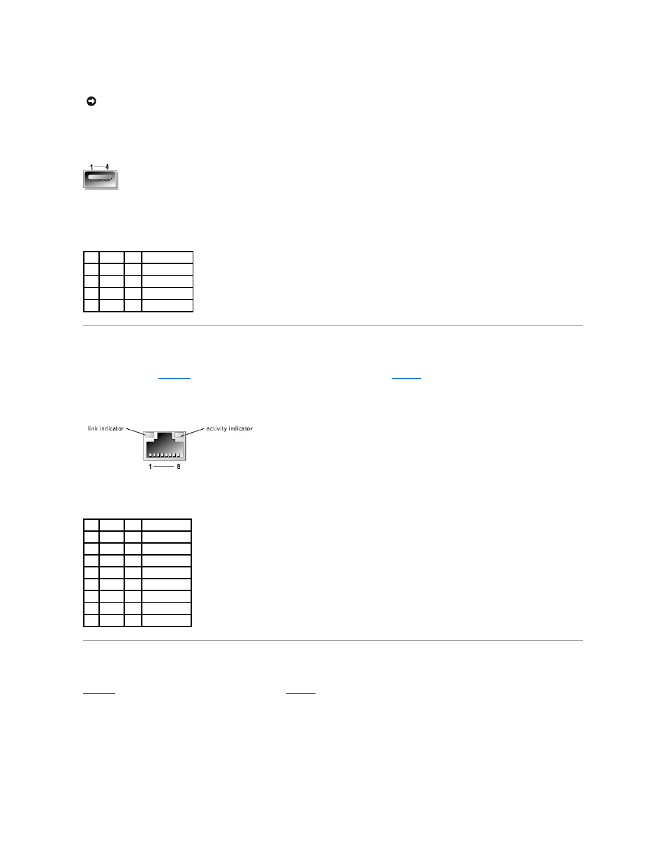
Figure B-6. USB Connector Pin Numbers
Table B-5. USB Connector Pin Assignments
RAC Ethernet Connector
The system's optional RAC circuitry is designed to provide remote access capabilities for the system. It is designed specifically to work with systems
management software.
illustrates the pin numbers for the RAC Ethernet connector and
defines the pin assignments for the connector.
Figure B-7. RAC Ethernet Connector
Table B-6. RAC Ethernet Connector Pin Assignments
Integrated NIC Connector
The system's integrated NIC functions as a separate network expansion card while providing fast communication between servers and workstations.
illustrates the pin numbers for the NIC connector and
defines the pin assignments for the connector.
Figure B-8. NIC Connector
NOTICE:
Do not attach a USB device or a combination of USB devices that draw a maximum current of more than 500 mA per channel or +5 V. Attaching
devices that exceed this threshold may cause the USB connectors to shut down. See the documentation that accompanied the USB devices for their
maximum current ratings.
Pin Signal I/O Definition
1
Vcc
N/A Supply voltage
2
DATA– I/O Data (–)
3
DATA+ I/O Data (+)
4
GND
N/A Signal ground
Pin Signal I/O Definition
1
TD+
O
Data out (+)
2
TD–
O
Data out (–)
3
RD+
I
Data in (+)
4
NC
N/A No connection
5
NC
N/A No connection
6
RD–
I
Data in (–)
7
NC
N/A No connection
8
NC
N/A No connection