Back-panel features, Figure 2, Scsi hard-drive indicator codes – Dell PowerEdge 1750 User Manual
Page 22
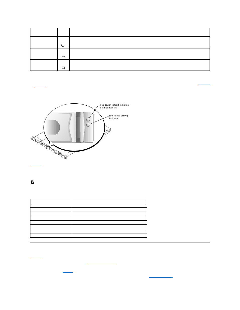
SCSI Hard-Drive Indicator Codes
If the optional ROMB card is activated, two indicators on each of the hard-drive carriers provide information about the status of the hard drives. See
. The SCSI backplane firmware controls the drive power
-on/fault indicator.
Figure 2-3. SCSI Hard-Drive Indicators
lists the drive indicator patterns. Different patterns are displayed as drive events occur in the system. For example, if a hard drive fails, the "drive
failed" pattern appears. After the drive is selected for removal, the "drive being prepared for removal" pattern appears, followed by the "drive ready for
insertion or removal" pattern. After the replacement drive is installed, the "drive being prepared for operation" pattern appears, followed by the "drive online"
pattern.
Table 2-3. SCSI Hard-Drive Indicator Patterns
Back-Panel Features
shows the controls, indicators, connectors, and expansion slots located on the system's back panel.
l
For information about the connectors, see "
System Board Connectors
" in "Jumpers and Connectors."
l
The blue and amber system status indicator combines the functions of the separate blue and amber system status indicators on the front panel. For
.
l
For information about the identification buttons located on the front and back of the system, see "
."
NOTE:
If you turn off the system using the power button and the system is running an ACPI-compliant operating system,
the system performs a graceful shutdown before the power is turned off. If the system is not running an ACPI-compliant
operating system, the power is turned off immediately after the power button is pressed.
Identification button
The identification buttons on the front and back panels can be used to locate a particular system within a rack. When one
of these buttons is pushed, the blue system status indicator on the front and back blinks until one of the buttons is
pushed again.
USB connector
Connects a USB 1.1-compliant device to the system.
Video connector
Connects a monitor to the system.
NOTE:
If the optional ROMB card is not installed, only the "drive online" indicator pattern appears. The drive-activity indicator also blinks when the drive
is being accessed.
Condition
Indicator Pattern
Identify drive
The green power-on/fault indicator blinks four times per second.
Drive being prepared for removal
The green power-on/fault indicator blinks two times per second.
Drive ready for insertion or removal Both drive indicators are off.
Drive being prepared for operation The green power-on/fault indicator is on.
Drive predicted failure
The power-on/fault indicator slowly blinks green, amber, and off.
Drive failed
The amber power-on/fault indicator blinks four times per second.
Drive rebuilding
The green power-on/fault indicator blinks slowly.
Drive online
The green power-on/fault indicator is on.