Replacing the camera and microphone assembly – Dell Vostro 2510 (Early 2009) User Manual
Page 47
www.dell.com/regulatory_compliance.
1. Follow the instructions in
Before Working on Your Computer
.
2. Remove the hard drive cover. See
for an illustration of the hard drive cover.
3. Remove the WLAN card (see
4. Remove the hinge cover (see
).
5. Remove the keyboard (see
6. Remove the display assembly (see
7. Remove the display bezel (see
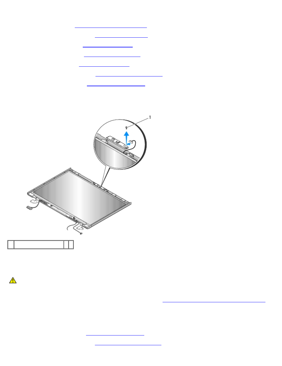
8. Remove the M2 x 3-mm screw that secures the camera/microphone assembly.
9. Lift the camera/microphone out of the top cover and disconnect the camera/microphone cable.
1 M2 x 3-mm screw (1)
Replacing the Camera and Microphone Assembly
CAUTION:
Before working inside your computer, read the safety information that shipped with your
computer. For additional safety best practices information, see the Regulatory Compliance Homepage at
www.dell.com/regulatory_compliance.
This procedure assumes that you have completed the removal procedure
Removing the Camera and Microphone Assembly
1. Connect the camera/microphone cable to the connector on the camera/microphone assembly.
2. Position the camera/microphone in the top cover and replace the M2 x 3- mm screw that secures the
camera/microphone assembly to the top cover.
3. Replace the display bezel (see
4. Replace the display assembly (see