Dell Inspiron 3500 User Manual
Page 144
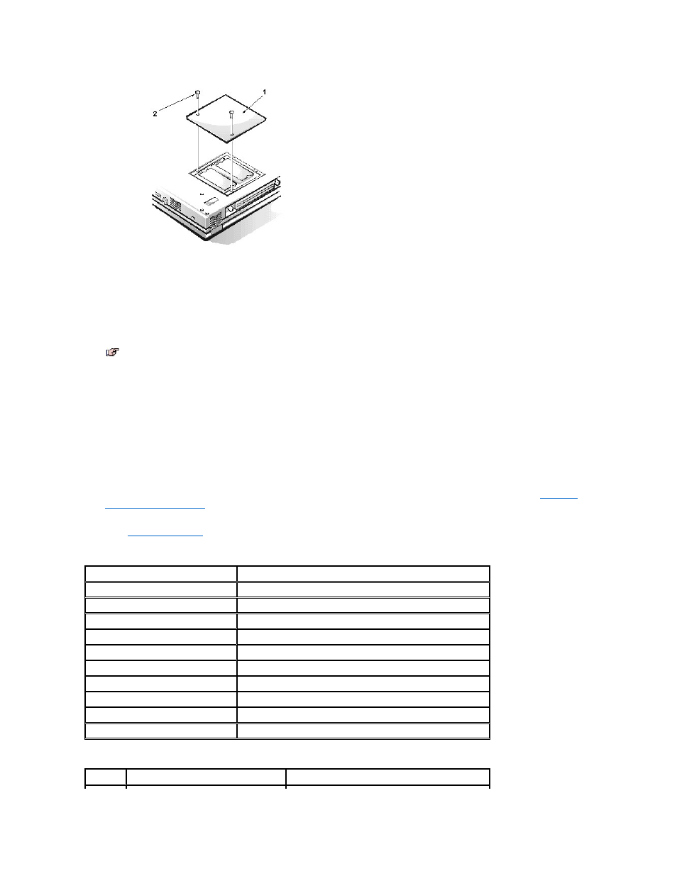
Remove the two screws from the memory module cover. Use your finger or a flat plastic tool to lift the cover out.
NOTICE: To prevent damage to the computer, do not use tools to spread the inner plastic tabs of the socket when you are
installing or removing a memory module.
7. If you are replacing a memory module, remove the existing memory module(s).
Carefully spread apart the inner plastic tabs of the memory module socket to disengage the module from the socket. The module pops up
slightly. Gently pull the memory module out of the socket.
8. Install the new memory module.
Align the notch in the edge connector with the slot in the center of the memory module socket. Press the memory module
’s edge connector
firmly into the socket, and push the module down until it clicks.
9. Replace the memory module cover, and replace the two screws.
10. Reinstall any batteries you removed in step 4. Reconnect the peripherals to the computer. Turn on the peripherals and then turn on the
computer. If you were using the AC adapter, reattach it as well.
As the computer boots, it detects the additional memory and automatically updates the system configuration information.
11. Confirm that the system configuration information reflects the newly installed memory by checking the System Memory option on the Main
menu of the Setup program.
To enter the Setup program, press
the memory modules may not be installed properly. Repeat steps 1 through 10 until the memory total is correct.
12. Run the RAM test group in the Dell Diagnostics to confirm that the installed memory modules are operating correctly.
For instructions on running the RAM test group in the Dell Diagnostics, see Chapter 4, "Running the Dell Diagnostics," in your
Reference
and Troubleshooting Guide.
13. If you have added additional memory to your computer, you need to delete and re-create the save-to-disk suspend file on your hard-disk
drive so that it is large enough to accommodate the new memory. For instructions, see the topic titled "Save-to-Disk Suspend File" in your
online
System User’s Guide
.
Upper Memory Map
Conventional Memory Map
1 Memory door
2 4-mm screw
NOTE: If one memory module is already installed and you are adding a second memory module, put the second module in the
available slot. Remove an existing module only if you are replacing it. Depending on how you ordered your computer, one or two
modules may already be installed.
Location
Description
10FFF0
Extended memory
100000
–10FFEF
High memory area
0F0000
–0FFFFF
System BIOS
0E0000
–0EFFFF
Video BIOS
0DC000
–0DFFFF
Available
0D0000
–0DBFFF
PC Card memory
0C0000
–0CFFFF
Available
0A0000
–0BFFFF
Video RAM
09FC00
–09FFFF
PS/2 mouse-data area
000000
–09FBFF
Conventional memory
Segment Address Range
Use