Lcd panel, And inverter – Dell Inspiron 2000 User Manual
Page 30
To replace the display-assembly latch, perform the following steps:
1. Carefully place the latch spring over the post on the display-assembly top cover.
You may need to use a small flat-blade screwdriver to place the spring over the post. Hold the spring on the post with the screwdriver while
performing the next step.
2. Holding the latch, stretch the spring slightly and set the display-assembly latch in place in the display assembly top cover.
3. Reinstall the bezel.
LCD Panel
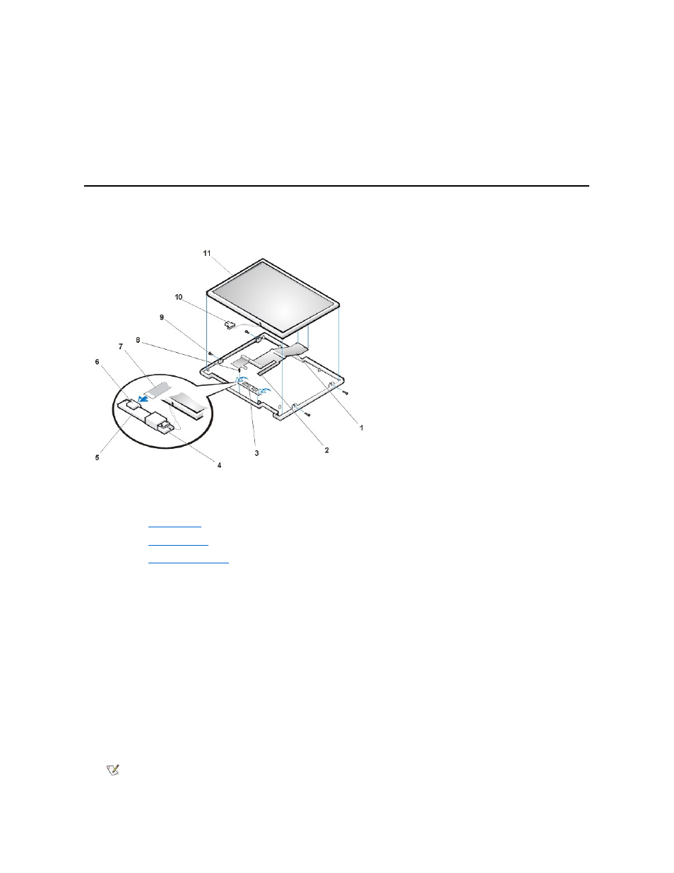
Figure 10. LCD Panel Removal
NOTICE: To avoid damaging the system board, you must remove the main battery before you service the computer.
1. Ground yourself by touching the unpainted metal surface of the I/O panel on the back of the computer.
2. Remove the
.
3. Remove the
4. Remove the
5. Remove the four M2 x 3.5-mm screws on the left and right sides of the display assembly that secure the LCD panel to the top cover (see
Figure 10).
6. Remove the M2 x 3.5-mm screw that secures the inverter to the top cover.
7. Lift and roll the inverter over (toward you), so you can view the component (non-Mylar) side of the inverter (see Figure 10).
8. Disconnect the narrow flex cable from the ZIF connector on the left side of the inverter.
9. Disconnect the two-wire back-light plug from the connector on the right side of the inverter (see Figure 10).
10. Remove the inverter.
11. Lift the LCD panel from the bottom edge, giving enough room to fit your hand between the LCD panel and the top cover.
12. Carefully peel the LCD flex cable away from the top cover.
13. Lift the LCD panel out of the top cover.
14. Lift up on the tape that is covering the wide flex-cable connector on the back of the LCD panel.
1 Wide flex cable
2 Narrow flex cable
3 Inverter
4 Back light plug
5 Inverter
6 ZIF connector
7 Narrow flex cable
8 M2 x 3.5-mm screw
9 M2 x 3.5-mm screws (4)
10 Back light plug
11 LCD panel
NOTE: Keep the tape for when you replace the LCD panel.