Display assembly latch – Dell Inspiron 2000 User Manual
Page 29
NOTICE: To avoid damaging the system board, you must remove the main battery before you service the computer.
1. Use a scribe to carefully pry the six rubber screw covers out of the six screw holes located along the top and bottom of the bezel on the front
of the display assembly (see Figure 8).
2. Remove the six M2 x 3.5-mm screws located at the top and bottom of the bezel on the front of the display assembly (see Figure 8).
3. Separate the bezel from the display-assembly top cover.
The bezel is secured by slot openings that snap into the display-assembly top cover. Carefully lift the inside edge of the bezel, working your
way around the inside perimeter, to unsnap and remove the bezel from the display assembly.
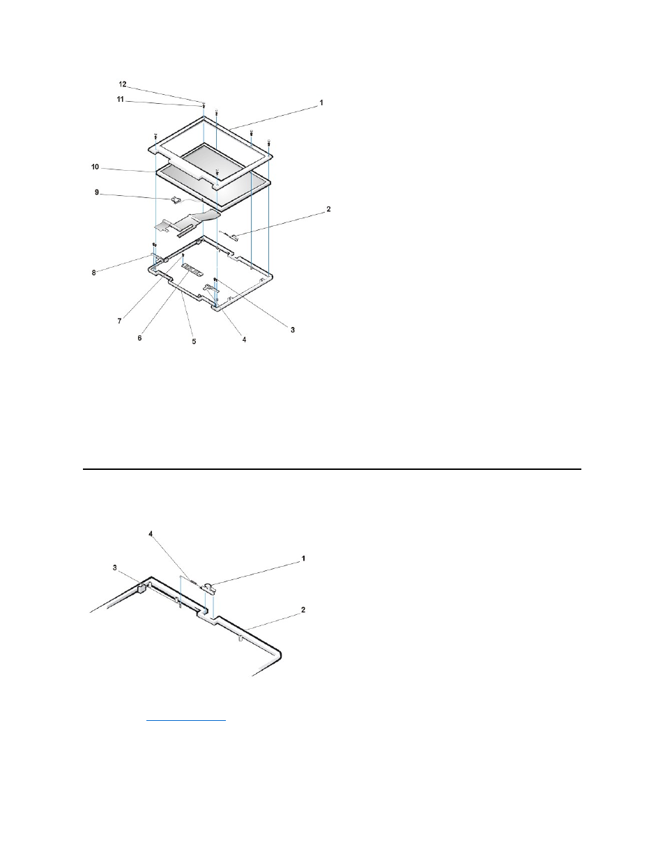
Display Assembly Latch
Figure 9. Display Assembly Latch Removal
NOTICE: To avoid damaging the system board, you must remove the main battery before you service the computer.
1. Remove the
2. Lift the display assembly latch of off the display-assembly top cover (see Figure 9).
3. Slide the latch spring off of the post on the display-assembly top cover (see Figure 9).
You may need to use a small flat-blade screwdriver to separate the latch spring from the post.
1 Display assembly bezel
2 Latch
3 M2.6 x 4-mm screws (4)
4 Right hinge
5 Display-assembly top cover
6 Inverter
7 M2 x 3.5-mm screw
8 Left hinge
9 Back light plug
10 LCD panel
11 M2 x 3.5-mm screw (6)
12 Large rubber screw covers (6)
1 Display assembly latch
2 Display assembly top cover
3 Post
4 Latch spring