Terminal assignment and commissioning, Mechanical mounting, Electrical connection – Baumer G0-GB-GXP5W/S/H-GXU5W/S User Manual
Page 47: Contact description, Pin assignment m12 connector
Manual_G0-GB-GXP5-GXU5_406_EN.docx
47/48
Baumer IVO GmbH & Co. KG
20.11.12
Villingen-Schwenningen, Germany
6. Terminal assignment and commissioning
6.1. Mechanical mounting
Shaft encoders
Mount the encoder with the help of the mounting holes and three screws (square flange: 4 screws)
provided at the encoder flange. Observe thread diameter and depth.
There is an alternative mounting option in any angular position by eccentric fixings, see under
accessories.
Connect drive shaft and encoder shaft by using an appropriate coupling. The shaft ends must not touch
each other. The coupling must compensate temperature and mechanical tolerances. Observe the
maximum permitted axial or radial shaft load. For appropriate couplings please refer to accessories.
Tighten the mounting screws firmly.
End shaft/hollow shaft encoders
Mounting by clamping ring
Prior to mounting the encoder open the clamping ring completely. Push encoder onto the drive shaft and
tighten the clamping ring firmly.
Adjusting element with rubber buffer
Push the encoder onto the drive shaft and insert the cylindrical pin into the adjusting element (customer-
mounted) and the rubber buffer.
Mounting angle
Push the encoder onto the drive shaft. Insert adjusting angle into the encoder’s rubber buffer and fasten
the mounting angle at the contact surface.
Stud screw
Push the encoder onto the drive shaft and insert the stud screw (customer-mounted) int
o the encoder’s
rubber buffer.
Spring washer
Fasten the spring washer at the mounting holes of the encoder housing using screws. Push the encoder
onto the drive shaft and mount the spring washer to the contact surface.
6.2. Electrical connection
6.2.1. Contact description
Pin
Assignment
CAN_L
CAN bus signal (dominant Low)
CAN_H
CAN bus signal (dominant High)
UB
Supply voltage 10...30 VDC
GND B
Ground terminal for UB
CAN_GND
Optional: GND for CAN Interface
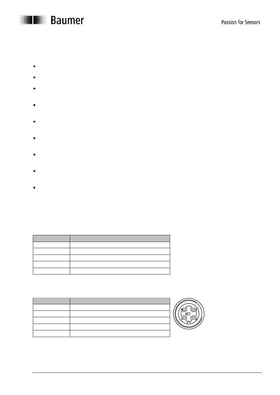
6.2.2. Pin assignment M12 connector
Pin
Assignment
1
GND B
2
UB
3
CAN_GND
4
CAN_H
5
CAN_L