Edge Lighting Light Channel, Surface Mount 24V RGB User Manual
Page 2
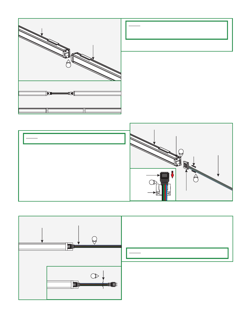
E
7: Carefully, connect light channel male end to light channel
female end, or refer to the flexible connector instruction.
7
LIGHT CHANNEL
ADDITIONAL
LIGHT CHANNEL
NOTE:
Multiple light channel can be connected together directly
by connecting male end of one to the female end of the other
one, or by using the flexible connectors up to a maximum of
25 feet.
F
8: Remove the two bottom screws (closest to the mounted
surface) of the selected power end cap.
9: Place the male end of the power cord in the cord grip if
connecting to the female end of the light channel or place
the female end of the power cord in the cord grip if
connecting to the male end of the light channel.
10: Push the cord completely into the light channel power end
cap pins and secure the cord grip to the light channel by
tightening the two screws (provided with cord grip) through
the cord grip into the light channel power end cap.
LIGHT CHANNEL
POWER END CAP
10
NOTE:
The power feed cable can be mounted to either the
female or male end of the channel.
SCREW
9
POWER CORD
CORD GRIP
2
POWER
CORD
CORD GRIP
9
I
LIGHT CHANNEL
POWER CORD
CUT
11
11
11: Cut the other end of the power cord (male or female) and
discard it. Strip the wire end for connecting it to the power
supply.
12: Follow the instructions provided with the RGB power supply
to power up the light channel.
NOTE:
If the RGB Light Channel does not light up, then remove
the cord and rotate 180° degrees and repeat steps 9 through 12.
DIRECT LIGHT CHANNEL CONNECTION
FROM ONE END TO ANOTHER END
LIGHT CHANNEL CONNECTION
USING FLEXIBLE CONNECTOR