Edge Lighting Soft Line Mounting Hardware for Indirect Lighting User Manual
Page 2
2
D
WALL
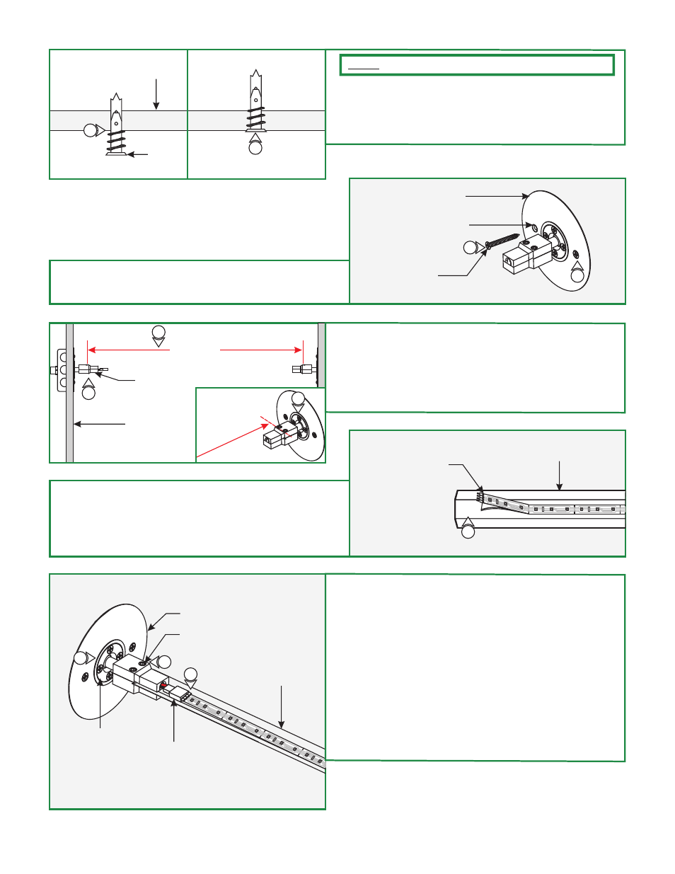
8
9
ANCHOR
8: Tap the anchors onto the marked points up to the threaded
portion with a hammer.
9: Screw in the threaded portion of the anchors with a Phillips
screwdriver.
NOTE:
Omit the steps 9 and 10 if installing to a wood surface.
E
10: Push the non-power feed turnbuckle into the 1.8" cutout
hole. Align the holes with the turnbuckles and secure it in
place with the two #8 screws.
10
10
NON-POWER FEED
TURNBUCKLE
BACKPLATE
CENTER HOLE
#8 SCREW
F
LENGTH
11: Slightly loosen (Do Not Remove) the four phillips screws
on adjustment link of each turnbuckle.
12: Measure the distance between the two Turnbuckles hex
screw heads to determine the Soft Line length.
13: Cut the Soft Line to determined length.
MEASURE FROM
SCREW HEAD
NON-POWER FEED
TURNBUCKLE
WALL
11
G
SOFT LINE
LED SOFT STRIP
15
14:
(pads provided) where the LED strip will be installed.
15: Remove the backing from the LED soft strip and firmly
press it down 2" away from one end of the soft line
channel.
Clean the Soft Line surface throughly with alcohol
16: Slightly loosen the two hex head screws on each
turnbuckle with provided Allen wrench.
17: Carefully insert channel with the male soft strip end into
the power feed turnbuckle and tighten the two hex head
screws to secure in place.
18: Insert the other end of the Soft Line onto the opposite
turnbuckle and tighten the two hex head screws.
19: Connect the power feed female connector completely onto
the soft strip male connector.
20: Tighten the four phillips screws on each turnbuckle
adjustment links for Soft Line to stay taut.
H
HEX HEAD SCREW
POWER FEED TURNBUCKLE
SOFT STRIP
16
POWER FEED
CONNECTOR
17
ADJUSTMENT
LINK
20
12
11