Edge Lighting Kurve Display Sign User Manual
Page 2
NOTE:
It is recommended another person hold the fixture while
the electrician connects the power to the fixture.
2
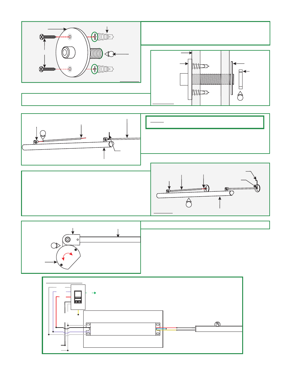
ANCHOR
F
8: Insert the base nipple into the hole and secure using
the two #8 screws provided.
9: Repeat step 8 for the other bases (without the nipple).
8
DRYWALL
#8 SCREW
NIPPLE
WALL
10: Power Feed Base Only: secure from behind the wall
using the large washer and nut.
G
SIDE VIEW
POWER
FEED BASE
WASHER
NUT
10
H
11: Feed the stem into the fixture hinges and secure by
tightening the M3 set screw with the 1.5MM Allen wrench.
For the power feed hinge carefully run the power
wires through the stem.
11
STEM
FIXTURE BODY
POWER
WIRES
HINGE
1.5MM ALLEN
WRENCH
12: While feeding the power wires into the base, slide the
stems into the bases. Secure the stems in place by
t
13: Make all the proper wire connections. Refer to the power
supply instructions for additional information.
(General wiring diagram below).
ightening the M4 set screw on the bases with 2MM Allen
wrench.
I
DRYWALL
FIXTURE BODY
STEM
HINGE
POWER
WIRES
2MM ALLEN
WRENCH
M4 SET
SCREW
J
14: Rotate the fixture head to properly luminate the sign.
STEM
HINGE
14
FIXTURE
HEAD
ANGLE/KURVE DISPLAY SIGN
GENERAL WIRING
BASE
INPUT
120VAC
GROUND
LIGHTOLIER:
ZP600FAM120
CONTROLLER
WHITE (NEUTRAL)
BLACK (HO
T)
RED 120VAC
(HOT)
GRAY (1-10V)
PURPLE (1-10V)
input 120VAC
WH (N)
BK (L)
input 0-10V
PUR
GRY
RED (24VDC+)
BLUE (RETURN-)
YELLOW (DIM RETURN-)
POWER SUPPLY (1)
PSB-96-010-24VDC
24VDC
12