Edge Lighting Light Channel Trim 1.6 User Manual
Page 2
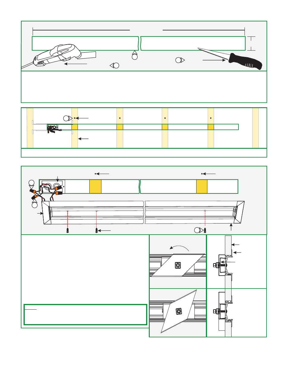
DRYWALL
2.25"
LENGTH OF
THE CHANNEL
DREMEL
MULTI-MAX
D
6" FIXED
JAB SAW
8: Mark the area where the channel will be located on the drywall.
9: Cut out the marked area(s) and install the drywall, using a "Dremel Multi-Max" with the "wood & drywall" cutting bit or a 6"
Fixed Jab Saw.
10: Install & finish drywall.
2
11: Mark the location of the studs to the drywall for future reference.
MARKING
STUD
E
8
11
9
9
12: Connect the red power supply (24VDC+) wires to each red
power wire with a wire nut.
13: Connect the black power supply (24VDC-) wires to each
black power wire with a wire nut.
14: Place the wire nut connections inside junction box.
15: Using the marked locations on the drywall, carefully make a
hole to channel using the provided square drill with counter
sink bit.
16: Secure the channel to the stud and the junction box with the
#6 drywall screws using the provided square recess bit.
F
POWER FEED
JUNCTION BOX
ENDCAP
#6 SCREW
CHANNEL
MARKING
MARKING
SIDE
VIEW
BACK
VIEW
TIGHTEN SCREW TO LOCK
CLIP INTO PLACE
CHANNEL
CONSTRAINT
CLIP (CONSISTS
OF A SCREW,
BASE, WING CLIP,
CAGE NUT,
& HEX NUT)
DRYWALL
AS SCREW IS
TIGHTENED,
CAGE NUT LOCKS
INTO PLACE
CAUSING
THE WING CLIP TO
SECURE TO
THE DRYWALL.
12
13
16
NOTE: If channel does not line up with a stud, use the provided
constraint clip kit to install to the drywall. Refer to diagram to the
right for reference. For alternate installation see “Section Two:
Alternate Installation w/Uneven Studs” on Page 4.