Edge Lighting Light Channel Trim 1.6 User Manual
Light channel trim 1.6, Installation instructions for, Important information
Installation Instructions for
Light Channel Trim 1.6
1718 W. Fullerton Ave
Chicago, IL 60614
Tel: 773-770-1195
Fax: 773-935-5613
www.edgelighting.com
© 2013 Edge Lighting. All Rights Reserved.
SAVE THESE INSTRUCTIONS!
IMPORTANT INFORMATION
904-LCT-1_6_02
1
LCT1.6-5WDC-_
1
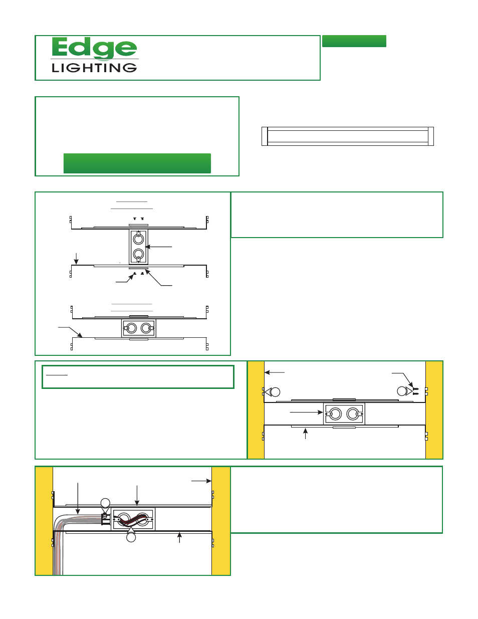
junction box (mounts to any side of the housing
depending on the orientation of the channel) and secure
them with the mounting brackets and two Phillips screws
provided.
: Mount each adjustable mounting bar to one side of the
- This fixture is wall or ceiling mount.
- This instruction shows a typical installation.
- If modifying channel length, please see “Section
Three: Modifying Channel Length” on Page 4 before
installation.
A
JUNCTION
BOX
JUNCTION
BOX
MOUNTING
BRACKET
ADJUSTABLE
MOUNTING BAR
PHILLIPS
SCREW
VERTICAL
ORIENTATION
HORIZONTAL
ORIENTATION
Section One: Installing The Channel
NOTE:
The adjustable mounting bars mount to studs that are
spaced 13" to 24" apart.
2: Select the location between the two studs for the junction
box to be mounted.
3: Place the adjustable mounting bars between the studs.
4: Make sure the lips on the adjustable mounting bars are
against the studs. Secure the adjustable bars to the studs
with the eight #8 screws.
JUNCTION
BOX
ADJUSTABLE
MOUNTING BAR
STUD
#8 SCREW
B
4
3
STUD
ADJUSTABLE
MOUNTING BAR
CONDUIT
JUNCTION BOX
C
5
6
5: Remove a knockout to install the power line conduit.
6: Install the conduit and run the low voltage 24V DC power
wires coming from the remote power supply to the
junction box.
7: Refer to the instruction provided with the power supply
along with the wiring diagram for proper wiring.