Edge Lighting Galleria Picture Light User Manual
Galleria picture light, Install the fixture, Installation instructions for
Installation Instructions for
Galleria Picture Light
904-GALLERIA-04
SAVE THESE INSTRUCTIONS!
- This product is wall mount for indoor locations.
- This product can mount to either a 4" square electrical box
with round plaster ring or an octagon electrical box.
- This product can be dimmed with a low voltage electronic
dimmer.
IMPORTANT INFORMATION
IMPORTANT SAFETY INSTRUCTIONS
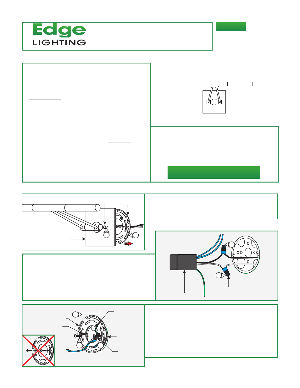
Install the Fixture
1:
fixture canopy.
2: Pull the crossbar assembly off of the fixture canopy.
Loosen and remove the two thumb nuts from the front of the
A
1
CROSSBAR
ASSEMBLY
FIXTURE CANOPY
THUMB NUT
3: Connect the white transformer wire to the neutral power
wire with a wire nut.
4: Connect the black transformer wire to the hot power wire
with a wire nut.
5: Place the transformer and transformer wires inside the
electrical box.
B
TRANSFORMER
WIRE NUT
3
4
To reduce the risk of fire, electrical shock, exposure to
excessive UV radiation, or injury to persons:
- Do not look directly at the lamp while the fixture is on.
- RISK OF FIRE: Use only the type of lamp and maximum
wattage indicated in this instruction manual.
- Never cover the halogen lamp with anything other than a
lamp shield provided by Edge Lighting and never place
flammable material close to the fixture.
- Never turn the fixture on and off by connecting and
disconnecting the halogen lamp.
- Do not touch the fixture head, shade or lamp shield while
the fixture is on. These surfaces may be VERY HOT.
- Do not touch lamp at anytime. Use a soft cloth instead as oil
from skin may damage lamp.
- It is normal for a new halogen lamp to produce minor
smoke when first turned on.
- Do not operate the luminaire with a missing or damaged
shield.
- Turn power off and allow to cool before replacing lamp.
GAL-PL-_
1718 W. Fullerton Ave
Chicago, IL 60614
Tel: 773-770-1195
Fax: 773-935-5613
www.edgelighting.com
© 2011 Edge Lighting. All Rights Reserved.
1
2
CROSSBAR ASSEMBLY
ELECTRICAL
BOX HOLE
C
6: Mount the crossbar assembly to the electrical box holes with
the provided #8-32 screws so that the two inner threaded
studs (spaced 2-1/8" apart) on crossbar are leveled
horizontally. Make sure to mount the #8-32 screws
just below the threaded studs for proper spacing.
7: Connect the transformer green wire to the crossbar assembly
ground screw. Make sure that the crossbar assembly is
grounded in accordance with local electrical codes.
7
#8-32 SCREW
GROUND
SCREW
2-1/8" APART
6
6
THREADED STUD
THE THREADED STUDS WILL INTERFERE
WITH MOUNTING SCREWS. MOUNT THE CROSSBAR
SLIGHTLY OFF CENTERED VERTICALLY.