Edge Lighting 2 Circuit Out-Riggers User Manual
Page 2
C
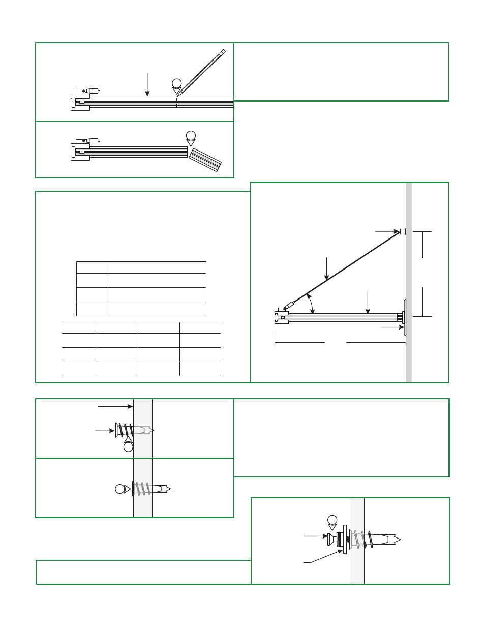
7: From the end of the out rigger arm, mark the point where
the
to be shortened. (Optional)
8: Cut at the marked point with a hacksaw.
9: Clean the inside and the outside burrs where cut.
out rigger arm needs
7
8
D
LENGTH(L) (H) FOR 30° (H) FOR 45° (H) FOR 60°
36"
24"
12"
21"
14"
7"
36"
24"
12"
62"
42"
21"
10: The cable post should be installed above the power feed
canopy so that there is a minimum of a 30° angle between
the out rigger arm and the aircraft cable to properly lock
the aircraft cable in position.
11: Use the tables below to determine the cable post position
relative to the out rigger arm for various angles.
ANGLE
EQUATION FOR HEIGHT (H)
30°
45°
60°
H = 0.6 x L
H = L
H = 1.7 X L
ANCHOR
WALL
14
13
12: Mark the cable post location on the wall above the canopy.
Using a hammer tap in the anchor on the marked
location up to the threaded portion.
14: Screw in the threaded portion of the anchor with a Phillips
screwdriver.
(See table above for measurements).
13:
E
F
15: Mount the integrated washer-nipple to the anchor
using the #8 screw provided.
INTEGRATED
WASHER-NIPPLE
#8 SCREW
15
2
30°
AIRCRAFT CABLE
CABLE POST
CANOPY
L
H
OUT RIGGER ARM
OUT RIGGER ARM