Useful info – Carlo Gavazzi WM4-96 User Manual
Page 56
▲
▲
56
Useful Info
List of Variables
51
GSM
58
59
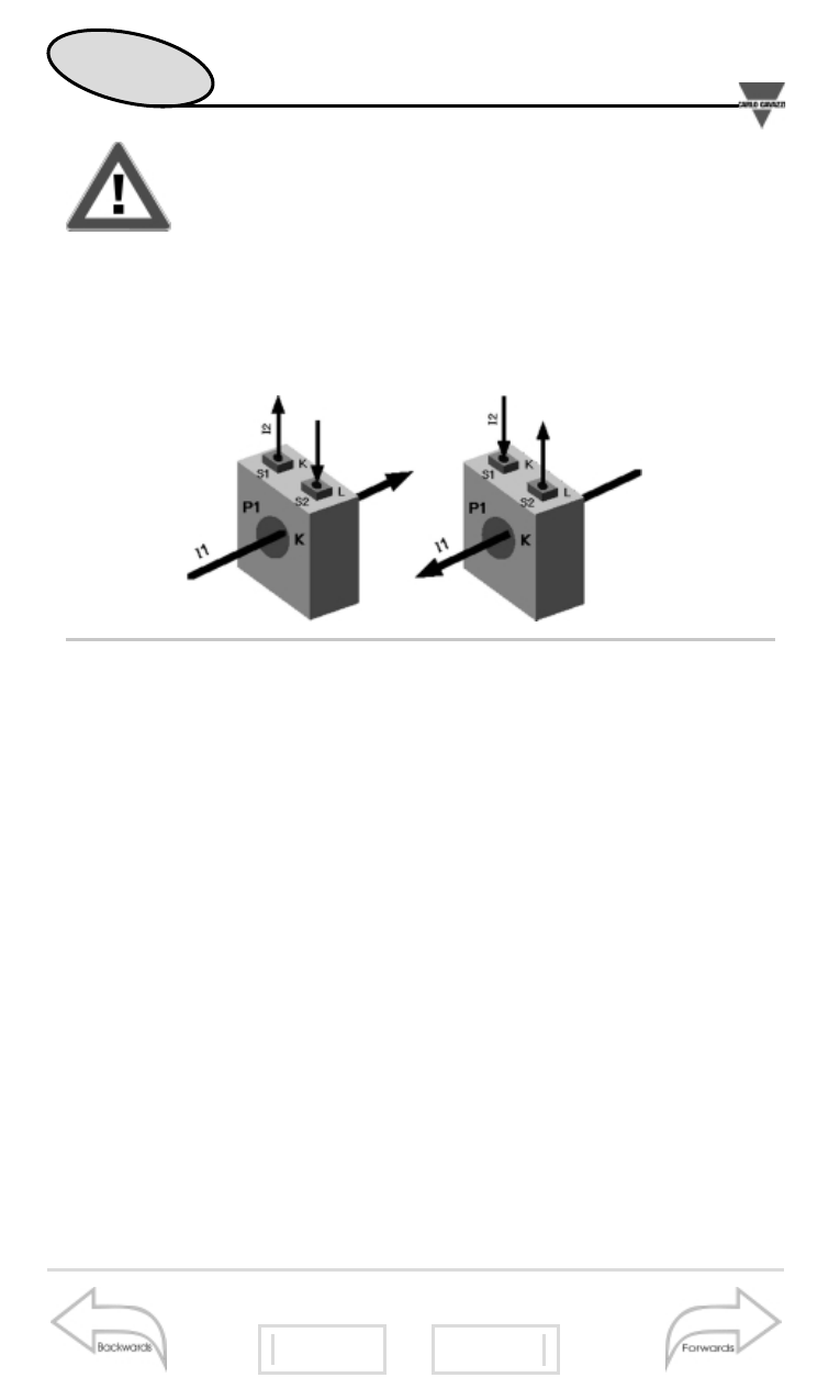
The variables measured by the instrument are correct
if the inputs have been connected according to the
right polarities (see figure below). Should the connec-
ction not be conforming to the right polarities, meas-
uring and retransmission errors may occur, both due to the
wrong direction of the current flowing in the primary/secondary
of the ammeter transformer being connected.
■
Application example of the digital filter
It’s necessary to stabilize the value of the displayed V
L-N
variable, that varies between 222V and 228V, maintaining a
4-dgt indication. The parameters of the digital filter must be set
as follows:
• DISPLAY: 4 digits
• RANGE: the variable may have variations within the average
amplitude value equal to ±1.3% of the rated value of this vari-
able which is obtained as follows: [(228-222) / 2 = ±3V, then
±3*100/231V= ±1.3% where 231V is the rated phase-neutral
value of an input at 400V)].
The “range” parameter, that is the action range of the digital fil-
ter, will be set at a value which is slightly higher than the per-
centage amplitude of the fluctuation: for example 1.5%.
• COEFFICIENT: if the new value acquired by the instrument is
within the action range of the filter, the new displayed value is cal-
culated by summing (algebraically) to the previous value the vari-
ation divided by the filtering coefficient. As a consequence, a