Install ground drive with pump, Determine ground drive location, Install strainer – Great Plains YP Fertilizer System User Manual
Page 10
Great Plains Mfg., Inc.
10
Fertilizer System
407-197M
02/29/2008
Install Ground Drive with Pump
This section installs most of the components of the 407-
134A kit.
Refer to Figure 18,
which depicts the planter with row units removed for clarity.
The ground drive pump is installed on the left wing, at or
near the plates supporting the drive-line clutch.
If you are replacing a hydraulic fertilizer pump as part of
this installation, perform the installation per the instruc-
tions for that update kit (407-149M).
Determine Ground Drive Location
These instructions do not specify a precise location for
mounting the new ground drive, due to the wide variety of
factory configurations and end user modifications.
The hose connections to the fertilizer feed line, strainer-
to-pump line and pump-to-distribution manifold permit
considerable flexibility in placement of strainer and pump.
The strainer requires a vertical surface with mounting
holes, typically the inside or outside of either plate of the
wing drive shaft bracket.
The optimal placement for the drive unit itself is halfway
between rows (row units or row unit pairs in twin-row).
These instructions assume that the strainer is to be
mounted inside the wing drive shaft brackets, on the
inboard plate, and the ground drive assembly is mounted
about a foot outboard of the wing drive shaft brackets.
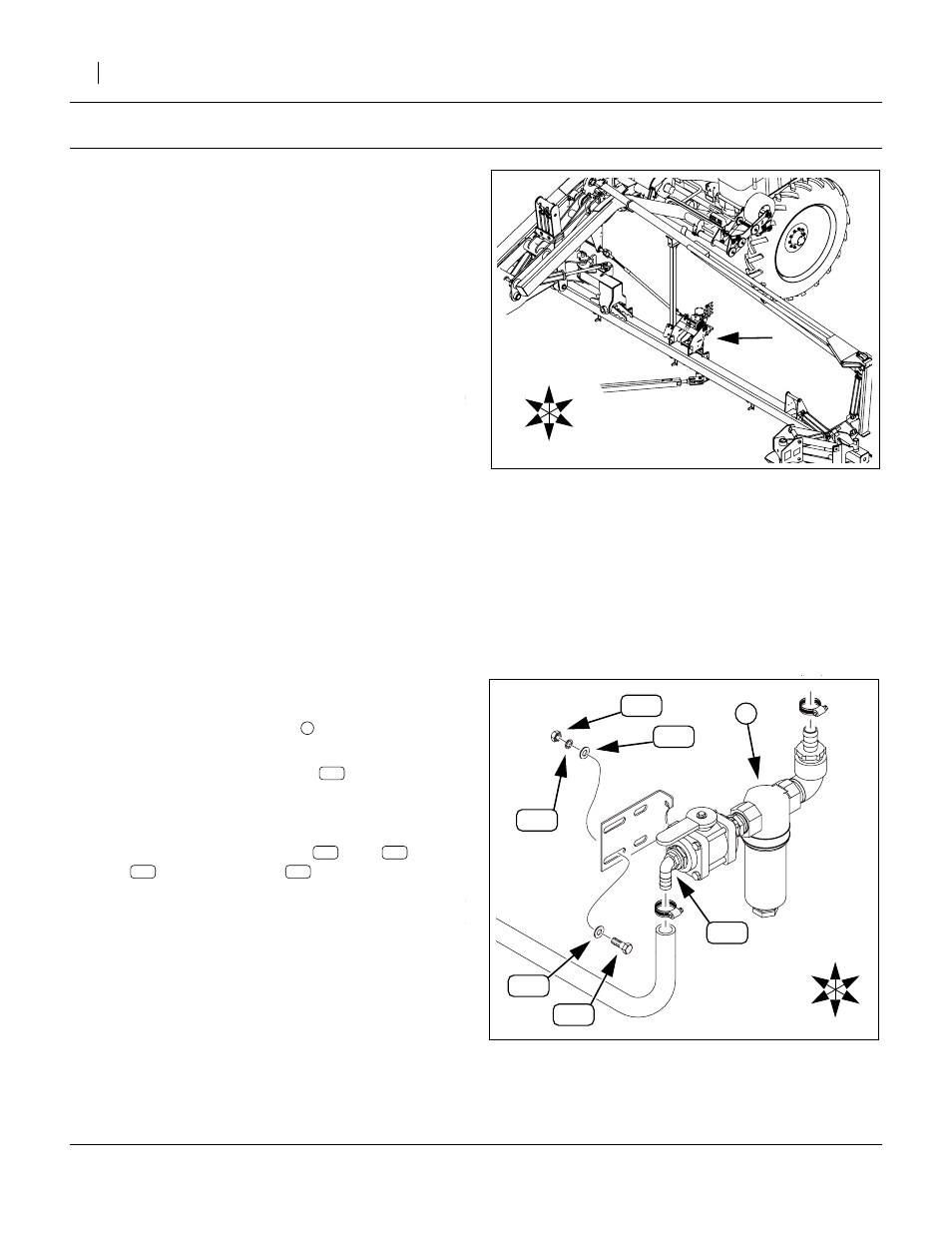
Install Strainer
52. Select the strainer assembly
, which does not have
a specific part number as an assembly.
53. If necessary, adjust inlet elbow
up (or down) so that the hose can exit the mount
area.
54. If the mount plate is pre-assembled to the valve,
remove the three sets of bolts
, nuts
, wash-
ers
and lock washers
U
D
F
B
L
R
Figure 18
Location of Components
25303
U
D
F
B
L
R
Figure 19
Strainer Components
27117
1