Verify drill fold, Level frame, Level frame side to side – Great Plains NTA3010 Predelivery Manual User Manual
Page 27: Check center height, Check wing height, Check center height check wing height, Caution
Great Plains Manufacturing, Inc.
Setup
25
11/06/2008
160-220M
Verify Drill Fold
Refer to drill Operator Manual (160-219M-A),
“Implement Fold” topic.
IMPORTANT !
Do not attempt to fold or unfold without review of cor-
rect operations in the Operator Manual. There are stop
bolts and wing locks, which, if not correctly used, can
lead to machine damage.
44. Slowly fold and unfold implement. Check for hydrau-
lic leaks. Be aware of any pinch points that might
cause damage or accelerate wear on hydraulic
hoses.
Level Frame
Level Frame Side to Side
45. Check that the lift hydraulics are fully charged and
bled of air (page 22). if there is any air in the system,
or the system has not recently been re-phased, you
will not get correct level.
46. Unfold and raise the drill. Remove lock channels. Set
the depth control stop valve to stop the drill, in lower-
ing, just before the coulters touch the ground.
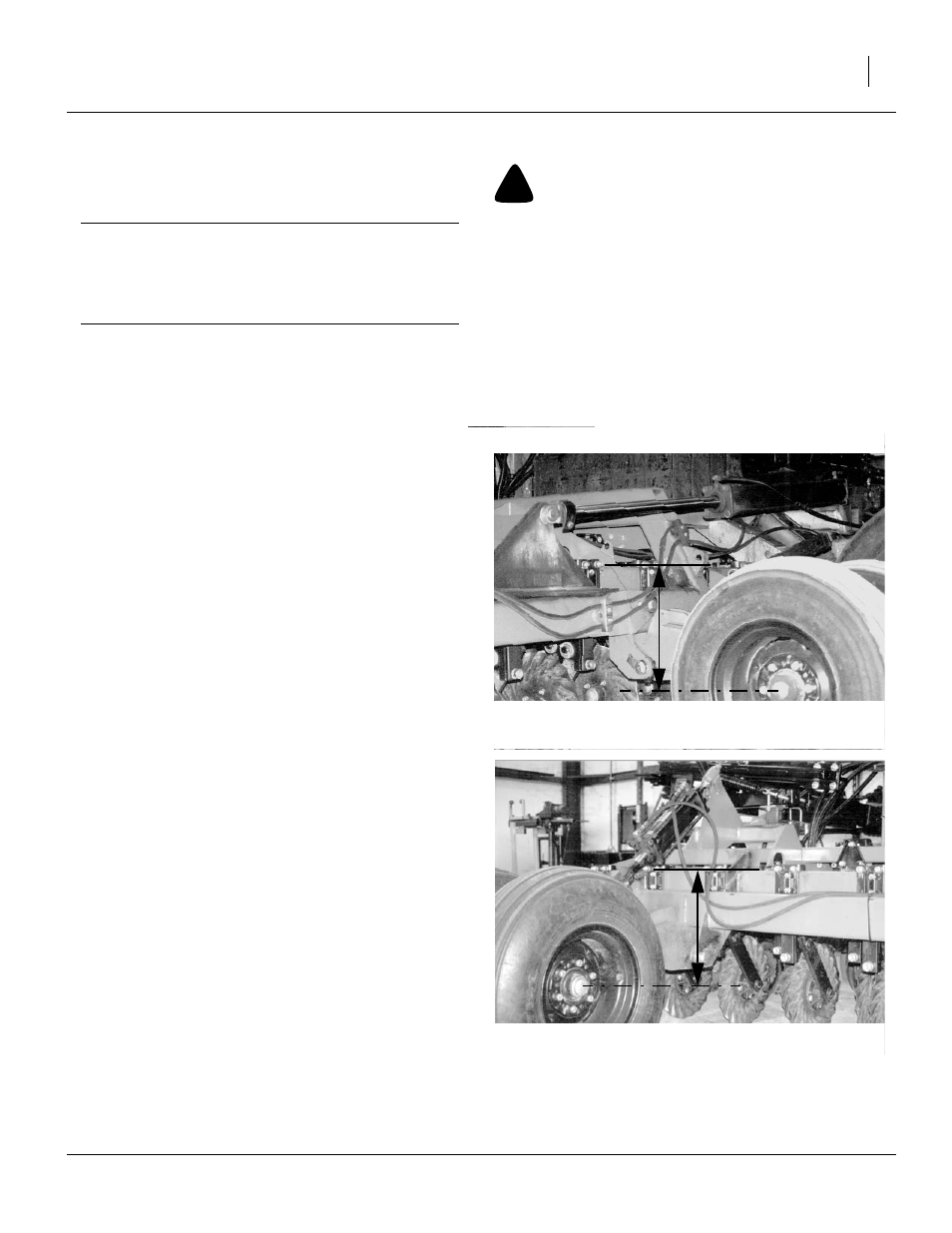
Check Center Height
47. Lay a straight edge across the top of the two coulter-
mount tubes on the center section (upper line in the
figure). Measure from the bottom of the straight edge
to the center of one rockshaft-wheel axle.
Note: The lowered rockshaft gauge wheel height is not
adjustable, so all adjustments are made relative to
this measurement.
Check Wing Height
48. Move the straight edge to one of the wings. Measure
the distance from the bottom of the straight edge to
the center of the wing-gauge-wheel axle.
49. If the wing height is the same, or less then than
3
⁄
16
in
(5mm) different, no adjustment is necessary. Con-
tinue at step 53. If adjustment is indicated, continue
at step 50.
!
CAUTION
Never fold implement unless transport locks are installed.
Figure 30
Frame Height Reference
16235
Figure 31
Check Wing Height
16236