Drill assembly, Wing to frame, Rockshaft to frame – Great Plains NTA3010 Predelivery Manual User Manual
Page 13: Wing to frame rockshaft to frame, Warning
Great Plains Manufacturing, Inc.
Air Drill Assembly
11
11/06/2008
160-220M
Drill Assembly
Wing to Frame
Start with the left wing.
17. Check that the pivot bushings:
890-011C BUSHING SPINDLE 1 1/2X1 1/4X1
are in place in center-section pivot tubes.
18. At each wing clevis
, drive out and save:
then remove and save two:
160-201H WING PIVOT PIN WELDMENT
19. Align wing clevises
with center-section pivot tubes
. Re-insert pivot pins
. Secure with roll pins
.
20. Repeat step 17 through step 19 for right wing
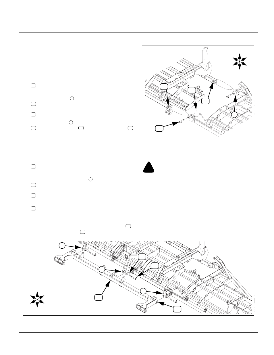
Rockshaft to Frame
21. Check that the pivot bushings:
890-011C BUSHING SPINDLE 1 1/2X1 1/4X1
are in place in the three rockshaft pivot tubes.
22. At each center section clevis
, drive out and save:
then remove and save three:
160-201H WING PIVOT PIN WELDMENT.
23. With hoist or forklift move the rockshaft:
161-074H NTA 35’ ROCKSHAFT WELDMENT
to the front of the implement and align each rock-
shaft pivot tube with the center-section clevis.
24. When the holes are aligned, re-insert pivot pins
and secure with roll pins
Figure 6
Wing to Frame Assembly
16222
U
D
F
B
L
R
1
Figure 7
Rockshaft to Frame Assembly
16223
U
D
F
B
L
R
!
WARNING
Crushing hazard. You may be severely injured or killed by the
rockshaft if it falls. Be certain the rockshaft is securely sup-
ported by a forklift or hoist.