Install lift hydraulics, Install wing gauge wheel cylinders – Great Plains NTA3010 Predelivery Manual User Manual
Page 18
16
NTA3010, NTA3510 and ADC
Great Plains Manufacturing, Inc.
160-220M
11/06/2008
Install Lift Hydraulics
Note: There are four different size cylinders supplied for
use with the NTA drill. Check part numbers and
bore sizes. Pin hardware may also be different for
rod and base ends of the same cylinder.
IMPORTANT !
Mounting cylinders incorrectly voids warranty and can
cause implement damage.
Install Wing Gauge Wheel Cylinders
Start with the right wing.
49. At the center section, untie the wing gauge-wheel
cylinders. Select the right cylinder:
810-221C CYL REP 4.25X12X1.5 ROD (TIE)
The gauge-wheel cylinders for the wings are labeled
4
1
⁄
4
in bore re-phasing. The right cylinder is the one
without the 161-112K depth-stop valve assembly
.
50. Remove and save the base-end pin hardware:
805-017C PIN COTTER 3/16 X 1 3/4 PLT
804-029C WASHER FLAT 1 SAE
805-239C PIN CLEVIS 1 X 3 5/16 HRD PLT
51. With the hydraulic ports facing up or inward, pin the
base end of the cylinder
to the right wing eyebolt
. Secure with clevis pin
, washer
and cotter
pin
. Hoses are routed at step 65.
52. Remove and save the rod-end pin hardware:
805-017C PIN COTTER 3/16 X 1 3/4 PLT
804-029C WASHER FLAT 1 SAE
805-159C PIN CLEVIS 1 X 3 1/8 GR5 PLT
53. Pin the rod end of the cylinder
to the right gauge
wheel lug
. Loosely hold in place with clevis pin
only. Leave rod end washer
cotter pin
off, to
ease the later task of hydraulic charging.
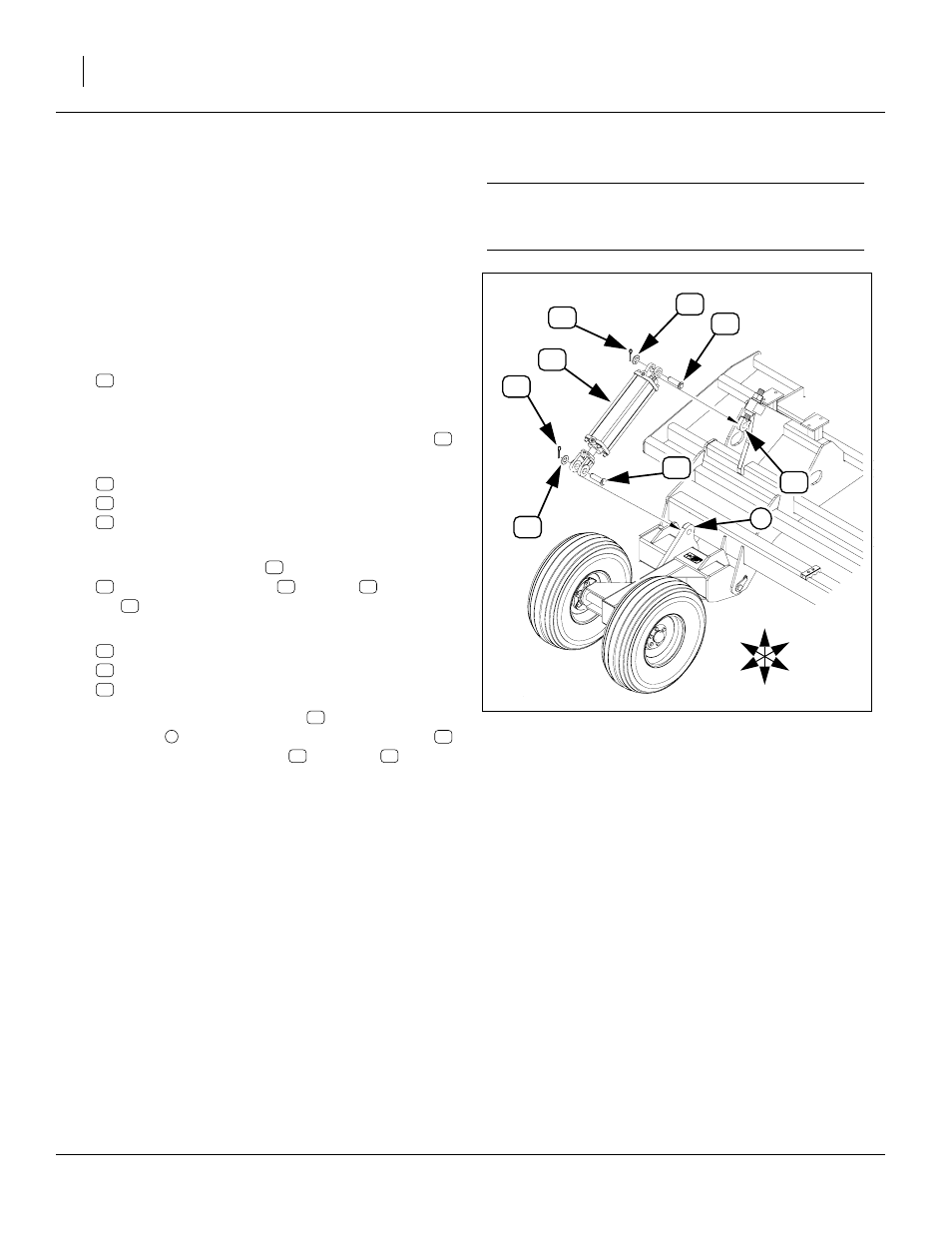
Figure 14
Right Gauge Wheel Cylinder
16425
1
U
D
F
B
L
R