Gauge wheel arms to wings – Great Plains NTA3010 Predelivery Manual User Manual
Page 14
12
NTA3010, NTA3510 and ADC
Great Plains Manufacturing, Inc.
160-220M
11/06/2008
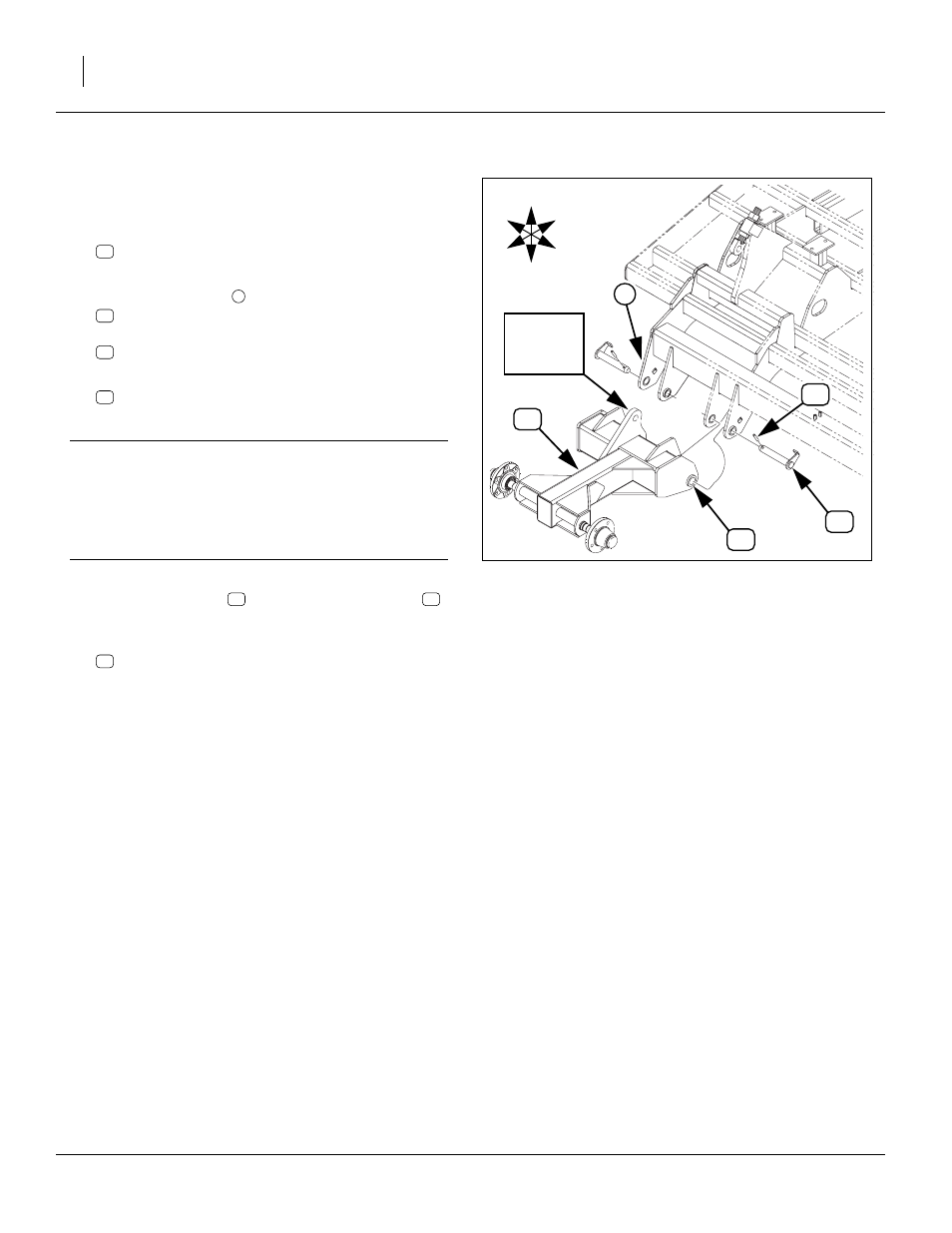
Gauge Wheel Arms to Wings
Start with the right wing.
25. Check that the pivot bushings:
890-011C BUSHING SPINDLE 1 1/2X1 1/4X1
are in place in pivot tubes on the gauge-wheel arms.
26. At each wing clevis
, drive out and save:
then remove and save two:
160-201H WING PIVOT PIN WELDMENT
27. Use forklift or hoist to move the gauge-wheel arm
NTA WING GAUGE WHEEL WLDMNT RH
to the front of the right wing.
IMPORTANT !
Determine which gauge-wheel arm is for the current
wing by looking at the cylinder lug on the wheel arm.
When standing behind the arm pivot tubes, the lug will
be to the outside (right of center for the right wing, and
left of center for left wing).
28. Align wing clevis and arm pivot tubes. When in place,
re-insert pivot pins
29. Repeat step 25 through step 28 for left wing gauge
wheel arm:
NTA WING GAUGE WHEEL WLDMNT LH
Figure 8
Wing Gauge Wheel to Frame
16424
U
D
F
B
L
R
Cylinder
Lug to
Outside