Install lift-assist cylinders – Great Plains NTA3010 Predelivery Manual User Manual
Page 19
Great Plains Manufacturing, Inc.
Air Drill Assembly
17
11/06/2008
160-220M
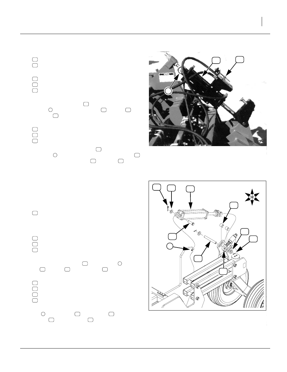
Refer to Figure 14 on page 16 and Figure 15
54. Select the left gauge wheel cylinder, which is:
161-112K NTA DEPTH STOP VALVE ASSY and
810-221C CYL REP 4.25X12X1.5 ROD (TIE)
55. Remove and save the base-end pin hardware:
805-017C PIN COTTER 3/16 X 1 3/4 PLT
804-029C WASHER FLAT 1 SAE
805-239C PIN CLEVIS 1 X 3 5/16 HRD PLT
56. With the depth stop on top of the cylinder, pin the
base end of the cylinder
to the left wing
eyebolt
. Secure with clevis pin
, washer
and
cotter pin
. Hoses are routed at step 65.
57. Remove and save the rod-end pin hardware:
805-017C PIN COTTER 3/16 X 1 3/4 PLT
804-029C WASHER FLAT 1 SAE
805-159C PIN CLEVIS 1 X 3 1/8 GR5 PLT
58. Pin the rod end of the cylinder
to the left gauge
wheel lug
. Loosely hold in place with clevis pin
only. Leave rod end washer
cotter pin
off, to
ease the later task of hydraulic charging.
Install Lift-Assist Cylinders
Start with the left caster assembly. Cylinders are identical
for both sides.
59. At the center section, untie the lift-assist cylinders.
Select one:
810-333C CYL REP 4.5X12X1.5 ROD 22.25L
The gauge-wheel cylinders for the wings are labeled
4
1
⁄
2
in bore re-phasing.
60. Remove and save the base-end pin hardware:
61. With the cylinder ports oriented up, pin the base end
of the lift-assist cylinder
to the top lug
, using a
pin
, washer
62. Locate, or remove and save the rod end hardware:
63. Pin the rod end of the lift-assist cylinder to the eye-
bolt
using the pin
washer
and cotter pins
hydraulic charging. Hoses are routed at step 65.
64. Repeat step 59 through step 63 for right lift-assist-
wheel arm.
Figure 15
Left Gauge Wheel Cylinder
16220
2
Figure 16
Lift-Assist Cylinder
28459
3
U
D
F
B
L
R