Detent and pressure plate adjust, Pressure plate adjustment, Edetent and pressure plate adjust – Great Plains 3S-4010HDF Operator Manual User Manual
Page 76
72
3S-4010HD and 3S-4010HDF
Great Plains Manufacturing, Inc.
196-522M
03/28/2012
E
Detent and Pressure Plate Adjust
Refer to Figure 85
The rear casters each have two independent adjust-
ments, which may need some attention as their internal
working surfaces wear over several seasons:
If the casters do not detent during straight-ahead move-
ment, first check the bolt
caster detent pin and/or detent plate as needed.
If the caster is oscillating during transport turns, adjust
the pressure plate bolt
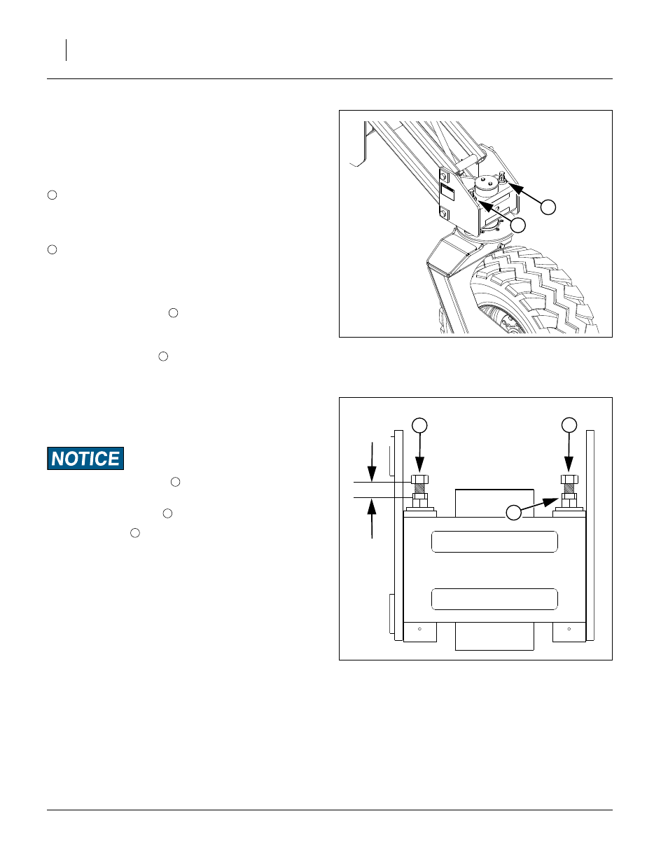
Refer to Figure 86
The factory setting for both adjustments is 1in (2.5cm)
from the face of the bolt head to the top of the weldment.
If pressure plate or detent components are ever
replaced, return the bolts to the factory setting.
Never adjust the detent bolt
to less than 1in.
Pressure Plate Adjustment
1.
Loosen the jam nut
2.
Turn the bolt
clockwise until the spring is fully
compressed.
3.
Back the bolt out
1
⁄
4
in (6mm).
4.
Tighten the jam nut.
FigureSpacer:
Caster Detent (on the outside, both sides):
This feature snaps the caster into the full trailing
position for straight-ahead movement. It helps keep
the drill running true in the field and in transport.
Caster Pressure Plate (on the inside, both sides):
This feature acts as a pivot brake, and helps prevent
caster oscillation during transport.
FigureSpacer:
Figure 85
Rear Caster Adjustments
(left side shown)
29224
2
1
1
2
FigureSpacer:
Figure 86
Rear Caster Adjustment Bolts
(right side shown)
29223
3
FigureSpacer:
1 in
2.5 cm
3