Section alignment – Great Plains 3S-4010HDF Operator Manual User Manual
Page 72
68
3S-4010HD and 3S-4010HDF
Great Plains Manufacturing, Inc.
196-522M
03/28/2012
E
Section Alignment
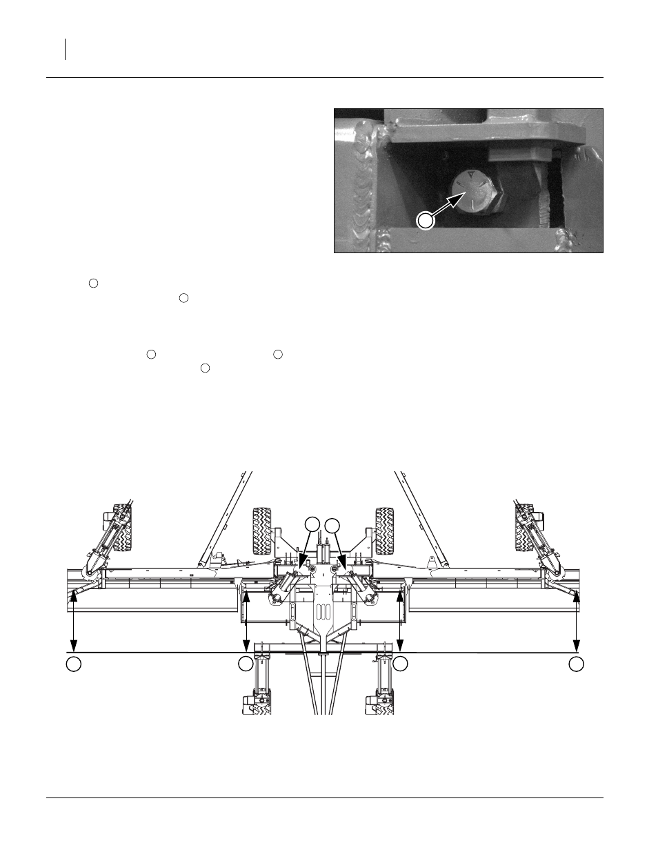
To check and adjust section alignment:
6.
Unfold drill, see “Unfolding” on page 22, and place a
block ahead of each wing gauge wheel. Pull drill for-
ward against blocks to rock frames back. Pull forward
until stop bolts are firmly against tool bars.
Check for proper alignment by running a string line
across back of drill toward outer ends of wings. Mea-
sure to the back face of the tool bar supporting the
row units.
For proper alignment, outside ends of wings (dimen-
sion
) should be 0-to-
1
⁄
4
in (0-to-6.4mm) ahead of
inside ends (dimension
To adjust section alignment, shorten or lengthen stop
bolts to change the contact point with the tool bars.
Adjust stop bolts
in or out until dimension
is 0 to
1
⁄
4
in greater than dimension
.
Lack of proper fold cylinder adjustment can cause diffi-
culties with gauge wheels by not allowing full rotation of
gauge wheel arm assemblies.
Note: If you have trouble getting a section aligned, it may
be necessary to adjust fold cylinders, see “Adjust-
ing Fold Cylinders” on page 65. Do not over-
adjust or you may cause fold latching problems.
Note: Section alignment, fold cylinder and tongue
spacer shim adjustments are closely interrelated
and may have to be adjusted in tandem. Adjust
fold cylinders to enable complete 90 degrees of
travel to latch wings and to unfold for section align-
ment. Then adjust tongue shims to remove as
FigureSpacer:
Figure 79
Stop Bolt
20317
7
FigureSpacer:
Figure 80
Section Alignment
27119
8
9
8
8