Initial setup, Install clutch switch module in cab, Shaft monitor – Great Plains 3S-4010HDF Operator Manual User Manual
Page 110: Einitial setup
106
3S-4010HD and 3S-4010HDF
Great Plains Manufacturing, Inc.
196-522M
03/28/2012
E
Initial Setup
These items need to be completed prior to first use, but
are not necessarily done by the dealer.
Install Clutch Switch Module in Cab
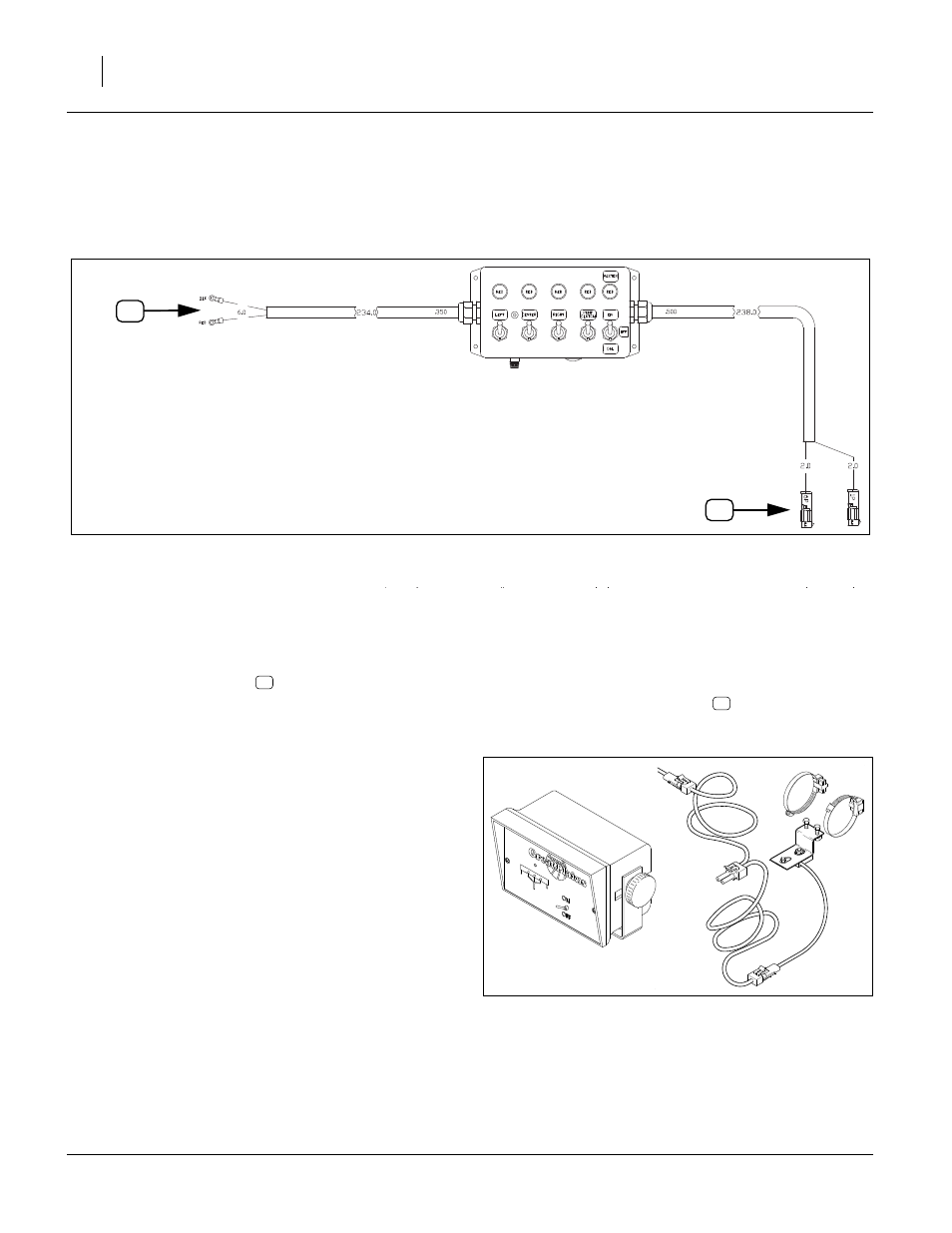
Refer to Figure 105 (dimensions are inches)
1.
Choose a tractor cab location where the module
does not obstruct vision, and the switches can be
safely operated during planting passes.
2.
Route the power leads
to a source of +12 Vdc
power capable of supplying 12.6A (3S) or 8.4A (2S).
Color code is: red+, black-.
Direct battery connection is acceptable; the control-
ler module has its own master switch and fuse.
3.
Use a cable tie to secure the power lead.
4.
Route the controller harness
to the tractor hitch.
Use 2 ties to secure the hitch lead.
Shaft Monitor
If a 3-channel shaft monitor (page 83) was ordered for
the drill, it was not factory-installed.
Consult the manual supplied with the shaft monitor for
installation.
FigureSpacer:
Figure 105
Cab Switch Module Cabling
28096
P
H
P
H
FigureSpacer:
18943
13178