Electroguard, Prefix 80 series exit device, Exit device plug-in connector installation – SARGENT FM8700 Surface Vertical Rod Exit Device User Manual
Page 25
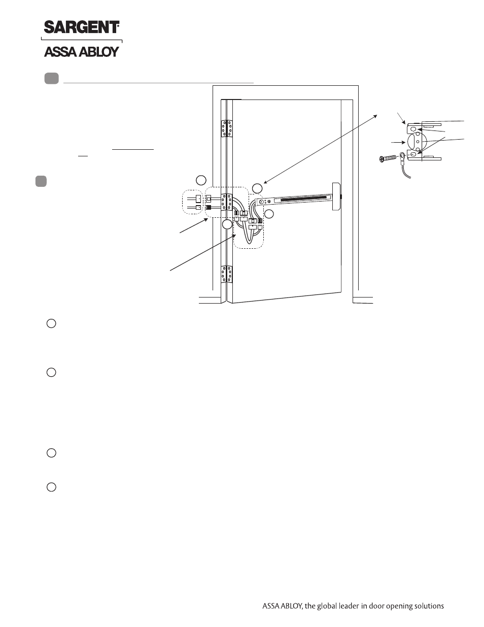
Pigtail harness assemblies with 8
& 4-pin connectors (shown). Pigtail
harness with 8-pin connectors
only may be supplied depending
on application.
Electric hinge with 8 & 4-pin connectors (shown).
Electric hinge with 8-pin connectors only may be
supplied depending on application
Rail-to-Hinge Raceway
harness with 8 & 4-pin
connectors
4
3
2
1
59- 80 Series Rail with
8 & 4-pin connector
and 3 flying leads
Note: Typical raceway location is
shown. Other locations may exist
depending on door type
Exit Device Plug-in Connector Installation
Insert bracket mounting screw through *ground ring terminal. Fasten mounting bracket with mounting bracket
screws (ring terminal).
Finish mounting exit device per instruction sheet provided.
Plug rail connectors into raceway connectors. Then feed through 1” hole
in door. Install rail mounting bracket with two screws supplied. Install rail
insert and end cap.
To insure trouble-free operation, check that the push rail can be fully depressed.
On vertical rod exit devices, adjust rods and check that the latch bolts do not go into hold- back position
until the push rail is fully depressed.
Go to (A) if wiring now. Go to (B) if wiring is to be done later .
A. Refer to Input/Output Terminations - Section 11 through Wiring Examples - Section 14
Wire to flying leads on pigtail harness(es) as required using connectors allowed by local code. Plug pigtail harness
connector(s) into electric hinge connector(s)
Feed harnesses through frame prep and mount electric hinge.
Ensure wiring is correct; apply power and test exit.
Refer to operating instructions in section 9.
B. Plug pigtail harness connector(s) into electric hinge connector(s).
Feed harness(es) through frame prep and mount electric hinge.
*Ring terminal must be grounded as indicated.
8
!
Plug raceway connector(s) into electric hinge connector(s) then feed through door prep.
Note: Electric hinge will have two 8-pin connectors or two 8-pin and two 4-pin connectors. Mount electric
hinge to door side only.
1
2
3
4
Mounting
bracket
1” dia. hole
in door
Screw
locations
Ring terminal
(from harness)
25 1-800-810-WIRE • www.sargentlock.com • A7690E
Copyright © 2013, Sargen
t Manufacturing Company
, an A
SS
A AB
LO
Y G
roup company
. All right
s reser
ved
.
Reproductions in whole or in par
t without express writ
ten permission of Sargen
t Manufacturing Company is prohibited
.
04/15/13
Electroguard
®
59- Prefix 80 Series Exit Device
- PR8700 Center & Top Latch Surface Vertical Rods for Pair of Doors PP8700 Center & Top Latch Surface Vertical Rods for Pair of Doors HC8700 Hurricane Code Surface Vertical Rod Exit Device NB8700 Top Latch Surface Vertical Rod 8700 Surface Vertical Rod Exit Device SP8600 Center & Top Latch Concealed Vertical Rods PR8600 Center & Top Latch Concealed Vertical Rods PP8600 Center & Top Latch Concealed Vertical Rods LR8600 Low Profile Center & Top Latch Concealed Vertical Rod Exit Devices LP8600 Low Profile Center & Top Latch Concealed Vertical Rod Exit Devices NB-WD8600 Concealed Vertical Rod Exit Device for Wood Doors WD8600 Concealed Vertical Rod Exit Device for Wood Doors NB-MD8600 Concealed Vertical Rod Exit Device for Metal Doors MD8600 Concealed Vertical Rod Exit Device for Metal Doors NB-MD8400 Series Narrow Style Concealed Vertical Rod MD8400 Series Narrow Style Concealed Vertical Rod LS8600 Low Profile Center & Top Latch Concealed Vertical Rods WS8900 Mortise Lock 8900 Mortise Lock Exit Device 8300 8888 Reversible Rim Exit Device 8800 Rim Exit Device 8500 Narrow Design Rim Exit Device HC8800 Rim Exit Device