Electroguard, Prefix 80 series exit device, 4installation instructions (continued) – SARGENT FM8700 Surface Vertical Rod Exit Device User Manual
Page 13: Refer to instruction sheet a6699
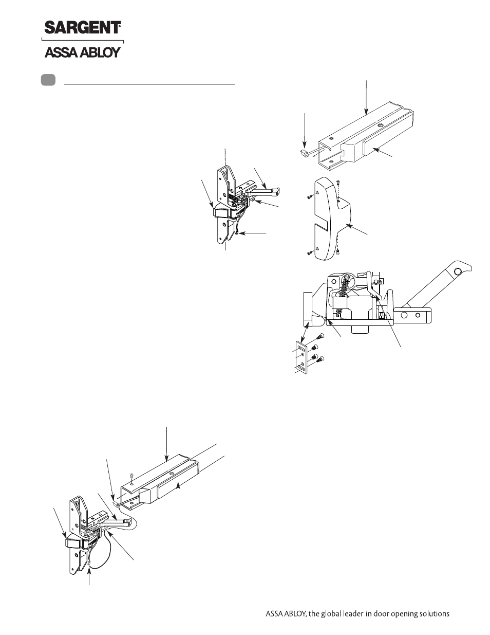
Rail wire &
connector
Push rail
Rail
assembly
C. Installing 59-8500/12-59-8500 Series Narrow Design
Rim Exit Device
Guarded
latchbolt
Chassis
arm
Vertical reference line
chassis
Wire
holder
Wire &
connector
Cover
Guarded
latchbolt
Rail wire
connector
Chassis
arm
Wire connector
Wire
holder
Rail
assembly
Push
rail
ATTACH RAIL ASSEMBLY
1. Depress chassis arm and slide rail assembly onto chassis
capturing the wire from the rail assembly in the wire holder.
Mount chassis.
2. Feed the rail wire along the same path as the chassis wire
and snap the ElectroLynx connectors together. Wire tie
excess in bottom of chassis
3. Apply covers.
Strike
Guard
Chassis wire &
connector
CAUTION – BEFORE STARTING:
•
Check hand of door (This device is
handed and not reversible)
•
Door should be fitted and hung
•
Verify box label for size of exit device,
function and hand
•
Install mullion in frame if used
IMPORTANT: Surface of door
where exit device is to be
applied must be flush. Clear
away any raised projections to
allow exit device to rest on flat
surface of door.
APPLY STRIKE–CRITICAL TO MAINTAIN
GUARDING OF LATCHBOLT
1. Determine proper position of strike by closing door
after mounting chassis and rail. Position strike on
frame or mullion, so that the latchbolt is extended/
engaged but the guard is held retracted. Mark loca-
tion of slotted holes and drill and tap (2) holes for
the oval head screws.
2. For the 59-8500 hardware, fasten the strike to the
frame or mullion with (2) star washers in between
strike and frame and tighten (2) screws.
Ensure
guard remains retracted when door is closed.
3. For the 12-59-8500 hardware, attach the strike
to the frame or mullion with (2) oval head
screws.
4.
Check strike placement again by closing
door and ensuring the guard is held retract-
ed (latchbolt guarded). Drill and tap (2) holes for
round head screws and fasten strike in place.
5. Ensure latchbolt is guarded by depressing it. The
latchbolt must fully project/extend when the door
is closed for the guarding to work. Finish installa-
tion per instruction sheet A6699 and Section 10
within this manual.
L
C
4
Installation Instructions (Continued)
Refer to Instruction sheet
A6699
13 1-800-810-WIRE • www.sargentlock.com • A7690E
Copyright © 2013, Sargen
t Manufacturing Company
, an A
SS
A AB
LO
Y G
roup company
. All right
s reser
ved
.
Reproductions in whole or in par
t without express writ
ten permission of Sargen
t Manufacturing Company is prohibited
.
04/15/13
Electroguard
®
59- Prefix 80 Series Exit Device
- PR8700 Center & Top Latch Surface Vertical Rods for Pair of Doors PP8700 Center & Top Latch Surface Vertical Rods for Pair of Doors HC8700 Hurricane Code Surface Vertical Rod Exit Device NB8700 Top Latch Surface Vertical Rod 8700 Surface Vertical Rod Exit Device SP8600 Center & Top Latch Concealed Vertical Rods PR8600 Center & Top Latch Concealed Vertical Rods PP8600 Center & Top Latch Concealed Vertical Rods LR8600 Low Profile Center & Top Latch Concealed Vertical Rod Exit Devices LP8600 Low Profile Center & Top Latch Concealed Vertical Rod Exit Devices NB-WD8600 Concealed Vertical Rod Exit Device for Wood Doors WD8600 Concealed Vertical Rod Exit Device for Wood Doors NB-MD8600 Concealed Vertical Rod Exit Device for Metal Doors MD8600 Concealed Vertical Rod Exit Device for Metal Doors NB-MD8400 Series Narrow Style Concealed Vertical Rod MD8400 Series Narrow Style Concealed Vertical Rod LS8600 Low Profile Center & Top Latch Concealed Vertical Rods WS8900 Mortise Lock 8900 Mortise Lock Exit Device 8300 8888 Reversible Rim Exit Device 8800 Rim Exit Device 8500 Narrow Design Rim Exit Device HC8800 Rim Exit Device